6
DIAGNOSTIC SERVICE MANUAL
Dometic
®
RM2604/2804
Refrigerators
SECTION 6
LP GAS COMPONENTS
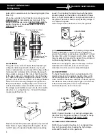
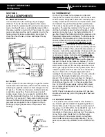
6.1 SHUT-OFF VALVE
It is the valve where the incoming LP gas supply is
attached. This valve is direct coupled to the selector
switch. When the selector switch is turned to the electric
mode, the shut-off valve is automatically closed. When
this same switch is turned to the LP gas mode, the valve
opens and allows gas flow and the electric circuit to the
heating elements is also automatically interrupted. To
check the shut-off valve, remove and inspect for any
obstructions.
6.2 FILTER
A filter is located in the inlet fitting to the gas thermostat.
It protects the internal valve portion of the thermostat by
collecting any particles and/or oil that could get into the
LP gas line. The filter can become saturated and cause
a restriction to gas flow. This could cause a lack of
cooling on gas mode. If you suspect a restriction, first
verify the thermostat (See Sec. 6.3) and by-pass screw
(See Sec. 6.4) are good. If these components are good,
remove the filter and replace with a new one if proper
gas pressure is supplied to the refrigerator and you
cannot get proper gas pressure at the pressure test
housing.
6.3 THERMOSTAT
On the LP gas mode, full line pressure is directed
through the thermostat to the burner until the thermostat
senses that the refrigerator cabinet has reached proper
cooling temperature. At that time an internal valve closes
and redirects the gas flow through the by-pass screw.
This reduces the amount of LP gas going to the burner
assembly. The gas flow remains in this “by-pass” mode
until the thermostat senses that the refrigerator cabinet
needs more cooling. Again, the thermostat directs LP
gas flow through the thermostat at full line pressure until
the cabinet temperature is sufficient. The thermostat is
calibrated by the manufacturer so that at mid-range the
cabinet temperature should be approximately 40 de-
grees Fahrenheit. To check the calibration of the
thermostat, place a container of water in the cabinet of
the refrigerator and operate at mid-range setting until the
thermostat is satisfied. Then, check the temperature of
the water. It should be approximately 40 degrees. We do
not recommend any calibration in the field. If calibration
is not correct, replace the thermostat. To check the
thermostat for proper gas flow, set the thermostat to
maximum and check the gas pressure at the pressure
test port. It should be line pressure, between 11 to 12
inches water column. If you have less than 11 inches of
water column pressure, the next step would be to shut
off the gas supply and remove the by-pass screw. Then
install a by-pass screw that does not have the small o-
ring on it. Next, turn on the gas supply and take a
reading. If the manometer now reads 11 inches of water
column, the thermostat is defective and must be re-
placed. If the by-pass screw test shows no change in
pressure, the problem lies in the filter (See Sec. 6.2), the
shut-off valve (See Sec. 6.1) or the gas supply (See
Sec. 5). Shut off the gas supply, remove the by-pass
screw, replace it with a proper one that has an o-ring
and turn the gas on.
NOTE: Check for leaks with an approved LP gas leak
solution whenever any part of the gas system has been
worked on.
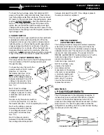
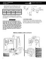
6.4 BY-PASS SCREW
The by-pass screw is a small brass screw located on
any Dometic gas thermostat that regulates gas flow in
the low flame mode. There are three common sizes of
this screw: S-17 (350 BTU), S-14 (325 BTU) and S-11
(300 BTU). To check the by-pass screw, connect a
manometer at the pressure test housing. The pressure
on low flame mode should be 3 to 5 inches water
column. Above 5 inches water column on low flame
mode could cause an over-cooling situation. The by-
pass screw used on the RM2604 and the RM2804 is S-
14.
MANUAL GA S
SHUTOFF VA LVE
TERMINAL BL OCKS
3-WAY ONL Y
ALL UNIT S
3 P RONG P LUG
FOR 120V A C
COVER
12 V olts
DC
Heater
12 V olts
DC
Reigniter
Lamp
SHUTOFF VA LVE
FILTER
COUPLING
GAS
THERMOSTAT
LINE

