7
DIAGNOSTIC SERVICE MANUAL
Dometic
®
RM2604/2804
Refrigerators
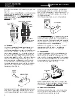
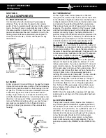
6.5 SAFETY VALVE
The safety valve is an assembly that shuts off the supply
of LP gas to the burner if the flame goes out for any
reason. This is to ensure that a concentration of un-
burned gas does not accumulate in the refrigerator vent
area. To check the safety valve, use a known good
thermocouple (See Sec. 6.6) and install into the safety
valve. Next, supply flame to the tip of the thermocouple
for 2 to 3 minutes while holding in on the safety valve
stem. Next, remove flame from thermocouple tip and
release safety valve stem. The safety valve should hold
in for at least 30 seconds. If it releases earlier than 30
seconds, replace the safety valve.
6.6 THERMOCOUPLE
The thermocouple is a component extending above the
burner assembly so the tip is in the path of the flame. It
will produce 14 to 30 millivolts DC in normal operation.
To check the thermocouple, use a known good safety
valve (See Sec. 6.5) and attach to the thermocouple.
Next, supply flame to the tip of the thermocouple for 2 to
3 minutes while depressing the safety valve. Remove
the flame and release the safety valve. The valve should
hold for at least 30 seconds. If it does not hold the safety
valve open for 30 seconds, replace the thermocouple. If
it does hold for 30 seconds or more, the thermocouple is
good, do not replace it.
NOTE: Be sure the tip on the thermocouple is clean.
6.7 BURNER
The burner is a slotted metal tube located below the flue
tube on the cooling unit. It should be level and the slots,
in the burner, should be directly below the flue tube. The
burner should be cleaned periodically, at least once a
year. To clean the burner, remove from the refrigerator
and check for any foreign residue that could cause a
deflection of the gas flow or the flame. Next, soak the
burner in an alcohol based solvent and allow to air dry.
After cleaning, reinstall in the refrigerator.
6.8 FLUE BAFFLE
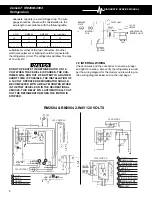
The flue baffle is designed to concentrate the heat, from
the gas flame, at a certain area of the flue tube. It should
be cleaned periodically, at least once a year. To clean,
remove from the flue tube and check for any damage,
then clean thoroughly. The length of the flue baffle
assembly (flue baffle and wire) for the RM2604 is 31-9/
16 inches and for the RM2804 is 37-1/8 inches. The flue
baffle itself for the RM2604 is 3/4 inch wide and 5-1/4
inches long, for the RM2804 is 3/4 inch wide and 6
inches long. The proper baffle position for the RM2604 is
1-5/8 inches from the burner to the bottom of the baffle;
for the RM2804 is 1-3/4 inches from the burner to the
bottom of the baffle.
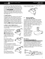
6.9 FLUE CAP
The flue cap is located at the top
of the flue tube and is attached
with a screw. It must be properly
attached or flame outage could
occur.
6.10 FLUE TUBE
The flue tube is a component of
the cooling unit. It must be
cleaned periodically, at least
once a year. To clean, remove
flue cap and flue baffle, then cover the burner and
clean by using a flue brush. Dometic Part Number
0151404001. If the flue tube becomes coated with scale
or residue from combustion of LP gas, the efficiency of
gas operation decreases.
NOTE: After cleaning be sure to reinstall the flue baffle
and flue cap.
6.11 ORIFICE
The orifice is a small brass fitting that has a ruby mem-
brane that is laser beam drilled and is mounted on the
gas line just prior to the burner. The orifice should be
cleaned periodically, at least once a year, by using an
alcohol based solvent and allowing to air dry. Never use
a drill bit or jet tip cleaner to clean any orifice as these
devices will damage the factory machined part and
create a potentially dangerous condition. The correct
orifice for the RM2604 is number 53 jet, for the RM2804
is number 58 jet.
NOTE: Always use the proper orifice. Never use a larger
orifice as this could cause a lack of cooling problem.
SECTION 7
WIRING
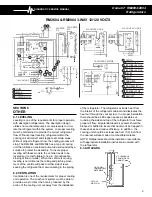
7.1 EXTERNAL WIRING
1. 120 volts AC connection: The refrigerator is
equipped with a three prong (grounded) plug for
protection against shock hazards and should be
plugged directly into a properly grounded three prong
receptacle. Do not cut or remove the grounding prong
from this plug.
2. 12-volt connection for igniter and interior light:
The connection is made to the terminal block marked
12 volts DC REIGNITER-LAMP. The interior light and
the igniter must be connected to a separate battery
circuit and will draw about 1 amp at 12 volts DC.
3. 12-volt DC connection for heater (3 -way models
only): This connection is made to the terminal block
marked DC VOLT HEATER. The refrigerator must be
connected to the battery circuit with two wires of

