background image

16

CERTIFIED VENT SYSTEM KITS

REFRIGERATOR

KIT

MODEL

NO.

COMPONENTS

PART NO.

RM2662

4A

Roof Base

3103633.XXX*

RM2663

Roof Cover

3103634.XXX*

RM2862

Lower Side Vent

3109350.XXX*

*

Fill in “XXX” with color code numbers. For color codes, contact your supplier.

For further information contact your dealer or distributor.

SPARE PARTS

The following list is a list of commonly used parts, which
should be available, if required, from your Dometic Ser-
vice Center.

A = RM2662;  B = RM2663;
C = RM2862.

Part No.

Description

  17 37 68-03/7

A B C Heater, 325W, 120V

  17 37 57-09/7

-

B -

Heater, 215W, 12V

200 74 19-21/7

A B C Jet, No. 58

293 06 97-07/9

A B C Burner, with conductor

293 20 93-03/8

A B C Handle (black)

293 21 06-01/2

A B C Lamp cover

293 25 75-05/9

A B C Door shelf, lower

293 25 76-06/5

A B -

Door shelf, 2 pieces

293 25 76-06/5

-

-

C Door shelf, 3 pieces

293 26 21-07/7

A B C Vegetable box

293 26 67-03/9

A B -

Baffle

293 26 67-04/7

-

-

C Baffle

293 27 81-01/2

A B C Electrode

293 27 50-11/6

A B C Door reversing kit,

right-left (black)

293 27 50-12/4

A B C Door reversing kit,

left-right (black)

293 27 50-15/7

A -

C Door reversing kit,

right-left (silver)

293 27 50-16/5

A -

C Door reversing kit,

left-right (silver)

Contact an authorized service center for
parts and repairs as needed.

Summary of Contents for RM2662

Page 1: ...his or any other appliance WARNING Improper installation adjustment alteration service or maintenance can cause injury or property damage Refer to this manual For assistance or additional information...

Page 2: ......

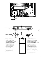
Page 3: ...icator Lamp GAS Mode Only F Temperature Indicator Lamps G Climate Control Switch LEGEND 2 WAY Model 1 Main Power Button ON OFF 2 AUTO GAS Mode Selector Button 3 Temperature Selector Button B AC Mode I...

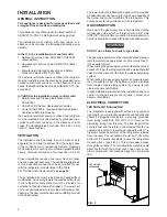
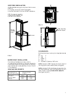
Page 4: ...t be provided for ventilation of heavier than air fuel gases The lower vent of the recommended kits is provided with proper size openings The flow of combustion and ventilating air must not be obstruc...

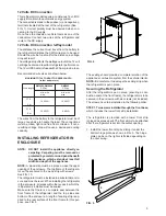
Page 5: ...The top frame of the refrigera tor will be anchored to the wood strip with screws See FIG 10 The refrigerator must be installed in a substantial enclo sure and must be level When installing the refri...

Page 6: ...rigerator is connected to the LP gas supply To test the gas safety shutoff proceed as follows 1 Start the refrigerator and switch to GAS mode See start up instructions 2 Check that the gas flame is li...

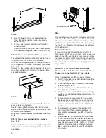
Page 7: ...to the roof material For ven tilation height see table VENTILATION HEIGHTS See Figures 9 and 10 METHODS OF INSTALLATION The method of installation is shown in FIG 9 It is essential that all maximum or...

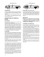
Page 8: ...l as the rolling and pitching movement of the vehicle will pass to either side of level keeping the liquid ammonia from accumulating in the evaporator tubing OPERATION Before starting the refrigerator...

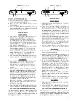
Page 9: ...including the interior light START UP INSTRUCTIONS A A continuous 12 volt DC supply must be available for the electronic control to function B Press the main power ON OFF button 1 to the DOWN position...

Page 10: ...open If the problem is still not corrected con tact a service center for assistance If the control is switched to AC or DC 3 way models only operation while the CHECK indicator lamp is on it will func...

Page 11: ...ood compart ment To prevent food from drying out keep it in covered dishes containers plastic bags or wrapped in aluminum foil Ice cubes can be made in the freezer compartment For faster ice making th...

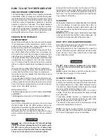
Page 12: ...Before working on the refrigerator make sure the AC voltage and DC voltage leads are disconnected Shut off the gas supply at the LP tank Disconnect the gas supply line at the rear of the refrigerator...

Page 13: ...agraph E item 1 13 WARNING DO NOT use a flame to check for gas leaks C Check the AMES control system by connecting dis connecting 120 volt AC power start stop the engine etc Compare the operation with...

Page 14: ...roper adjust ments and unfavorable installation conditions Contact service point or distributor service dept for assistance CHANGING DOOR HINGES FROM ONE SIDE TO THE OTHER The refrigerator is equipped...

Page 15: ...15...

Page 16: ...ter 325W 120V 17 37 57 09 7 B Heater 215W 12V 200 74 19 21 7 A B C Jet No 58 293 06 97 07 9 A B C Burner with conductor 293 20 93 03 8 A B C Handle black 293 21 06 01 2 A B C Lamp cover 293 25 75 05 9...

Page 17: ...side at the desired position Slide the wire shelf to the left The right hand side of the shelf will come loose Slide the shelf into the holes on the right hand side Lower the right hand side of the wi...

Page 18: ...18 RM2662 RM2862 RM2663...

Page 19: ...19...

Page 20: ...20 MO FO 0448...

Reviews: