background image

15

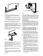
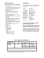
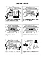
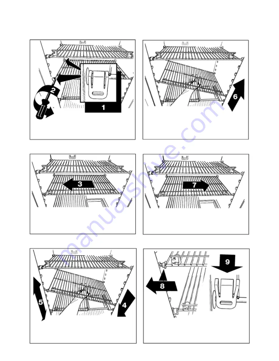
Put a screwdriver into the slot of the shelf lock.
Turn the screwdriver counterclockwise.
Remove the shelf locks from the wire shelf.

Insert the ends of the wire shelf on the left-hand
side at the desired position.

Slide the wire shelf to the left.
The right-hand side of the shelf will come loose.

Slide the shelf into the holes on the right-hand
side.

Lower the right-hand side of the wire shelf and
let the left-hand side slide out of the holes in the
wall.

Slide the plastic plugs into the holes of the wall.
Snap the shelf locks onto the wire shelf.

Positioning of shelves

Summary of Contents for RM3862

Page 1: ...ance WARNING Improper installation adjustment alteration service or maintenance can cause injury or property damage Refer to this manual For assistance or additional information consult a qualified in...

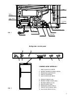
Page 2: ......

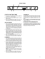
Page 3: ...AUTO COLD 1 2 3 4 5 COLDEST CLC LAC A C G E F 1 2 3 4 5 Refrigerator control panel LEGEND 2 WAY AES Model 1 Main Power Button ON OFF 2 AES AUTO GAS Mode Selector Button 3 Temperature Selector Button...

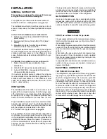
Page 4: ...utside at floor level in the refrigerator compartment must be provided for ventilation of heavier than air fuel gases The lower vent of the recommended kits is provided with proper size openings The f...

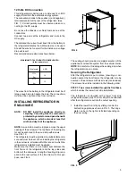
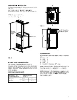
Page 5: ...rigerator must be installed in a substantial enclo sure and must be level When installing the refrigerator in the enclosure all areas within the recess in which the refrigerator is installed must be s...

Page 6: ...nected to the LP gas supply To test the gas safety shutoff proceed as follows 1 Start the refrigerator according to the instructions and switch to GAS mode See start up instructions 2 Check that the g...

Page 7: ...r side vent to the roof material For ven tilation height see table VENTILATION HEIGHTS See Figures 9 and 10 METHODS OF INSTALLATION The method of installation is shown in FIG 9 It is essential that al...

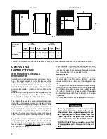
Page 8: ...he vehicle is moving the leveling is not critical as the rolling and pitching movement of the vehicle will pass to either side of level keeping the liquid ammonia from accumulating in the evaporator t...

Page 9: ...has automatically switched to the GAS mode 2 If the CHECK indicator lamp D illuminates and the GAS mode indicator lamp C is off the controls have failed to ignite the burner in the GAS mode GAS operat...

Page 10: ...ee or four times If repeated attempts fail to start the LP gas operation check to make sure that the LP gas supply tanks are not empty and all manual shutoff valves in the lines are open If the proble...

Page 11: ...the freezer compartment Ice will be made more rapidly if the thermostat is set at its highest position It is a good idea to do this a few hours before the antici pated need for ice but be sure to move...

Page 12: ...efrigerator make sure the AC voltage and DC voltage leads are disconnected Shut off the gas supply at the LP tank Disconnect the gas supply line at the rear of the refrigerator see FIG 1 Always use a...

Page 13: ...ace to take the LP gas pressure is at the test port just ahead of the burner jet See FIG 12 E Inspect the flue baffle It should be reasonably clean and free of soot Heavy soot formation indicates im p...

Page 14: ...sed parts which should be available if required from your Dometic Ser vice Center Part No Description 17 37 68 03 7 Heater 325W 115V 200 74 19 21 7 Jet No 58 293 06 97 07 9 Burner with conductor 293 1...

Page 15: ...side at the desired position Slide the wire shelf to the left The right hand side of the shelf will come loose Slide the shelf into the holes on the right hand side Lower the right hand side of the wi...

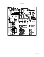
Page 16: ...16 RM 3862 MO FO 0309...

Reviews: