25
10.5 Shut off arm
The shutoff arm is cam driven. It operates a switch to con-
trol the quantity of ice produced. During the ejection cycle
the arm is raised and lowered during each of the two revo-
lutions of the timing cam. If the shutoff arm comes to rest
on top of the ice in the storage bin during either revolution,
the switch will remain open and stop the ice maker at the
end of that revolution. The arm has a manual shutoff built
into the linkage; by raising the arm as high as possible, it
will lock in that position until forced down. If the arm and
switch do not operate properly, check for damage and re-
pair or replace parts as necessary.
10.6 mold Switches
The three switches are single-pole, double-throw style.
They are identical and interchangeable. The holding
switch assures completion of a revolution once a cycle
has started. The water valve switch opens the water
valve during the fill stage of the cycle. NOTE: This is the
only adjustable component of the ice maker. If you use a
double throw switch, DO NOT use the N.O. terminal. The
shutoff switch stops the ice maker’s operation when the
storage bin is full.
10.7 timing motor
This is a low-wattage, stall-type motor which is geared to
the timing cam and ice ejector. It is a one RPM motor. To
check the motor, disconnect power to the appliance and
test for continuity between the two leads. If you DO NOT
have continuity, replace the motor. If you have continuity
and the motor runs, DO NOT replace.
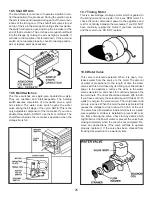
10.8 Water Valve
This valve is solenoid operated. When it is open, it re-
leases water from the source to the mold. The amount
of water is proportional to the length of time the water
valve switch is held closed by its timing cam. Disconnect
power to the appliance, remove the wires to the water
valve solenoid coil, and check for continuity between the
two terminals. The ohms should be between 200 to 500.
If you have continuity, the solenoid is good. It takes 10-15
watts to energize the solenoid coil. The mold heater and
coil are in series. When the mold heater is activated, this
causes the voltage to drop to about 105 VAC at the coil.
The valve has a flow washer inside which acts as a pres
-
sure regulator. A strainer is installed to prevent dirt, rust,
etc, from entering the valve. Check for any debris which
might obstruct the flow of water, or prevent the valve from
closing completely when the circuit is not energized. Re-
move any obstructions. If the valve still fails to operate
properly, replace it. If the valve has been cracked from
freezing this would not be a warranty item.
Summary of Contents for RM3962
Page 15: ...14 RM3762 RM3962...
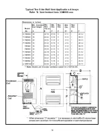
Page 20: ...19 Typical Two Side Wall Vent Application Always Refer To Vent Instructions 3308666 xxx...
Page 23: ...22...
Page 28: ...27...
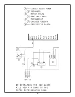
Page 29: ...28 ICE MAKER TYPICAL WIRING DIAGRAM...
Page 33: ...32...


