2
Page no.
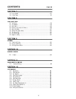
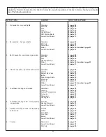
dIagnoStIc floW cHart
.............................................................................
4
contentS
SectIon 1
oPeratIon
Refrigerator Operation ........... .....................................................................
6
SectIon 2
ac Voltage
AC Voltage Requirements................ ...........................................................
9
SectIon 3
ac comPonentS
Heating Element ....................... ...............................................................
10
SectIon 4
dc Voltage
DC Voltage Requirements ............... ........................................................
10
SectIon 5
dc comPonentS
5.1 Thermistor ............................ .....................................................
11
5.2 Solenoid Valve.................................... .......................................
11
5.3 Igniter ........................ ................................................................
11
5.4 High Voltage Cable ................................. ..................................
12
5.5
Electrode ....................................................................................
12
5.6 Control Panel .............................................................................
12
5.7
Climate Control Heater ...............................................................12
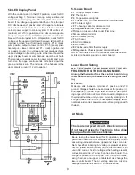
5.8 LED Display Panel ....................... .............................................
13
5.9 Lower Board ....................... .......................................................
13
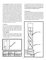
5.10 Door Switch ......................... ......................................................
15
5.11 Fuses ................................ ........................................................
15
5.12 Thermofuse ............... ................................................................
15
SectIon 6
lP gaS
LP Gas Requirements ................... ......................................................
16
SectIon 7
lP gaS comPonentS
7.1 Manual Gas Shut-Off Valve .................. .....................................
16
7.2 Orifice ...................................
.....................................................
16
7.3 Thermocouple .............................. .............................................
16
7.4 Burner .................................... ...................................................
17
Summary of Contents for RM3962
Page 15: ...14 RM3762 RM3962...
Page 20: ...19 Typical Two Side Wall Vent Application Always Refer To Vent Instructions 3308666 xxx...
Page 23: ...22...
Page 28: ...27...
Page 29: ...28 ICE MAKER TYPICAL WIRING DIAGRAM...
Page 33: ...32...

