background image

5

DIAGNOSTIC SERVICE MANUAL

DOMETIC® RM7030/RM7732

Refrigerators

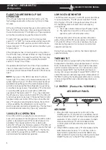
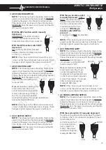
AES FULLY AUTOMATIC MODE

Turn switch "C" to the "ON" position. The bulb above

push-button "A" will light up green, indicating that the

control system is in the fully automatic mode. In this

mode, 120 volts AC operation has first priority, meaning

the refrigerator will operate on 120 volts AC whenever it

is available. If 120 volts AC is not available, the system

will automatically switch to LP gas operation. The

thermostat inside the refrigerator cabinet cycles the

element/burner as required to maintain the desired

temperature.

NOTE: The AES controls will automatically go to the

fully automatic mode each time switch "C" is turned

"ON".

LP GAS OPERATION

When there is no electrical power available (120 volts

AC) or if the indicator lamp above button "B" is ON, the

AES system will switch to LP gas operation. When the

thermostat in the refrigerator cabinet calls for cooling,

the following sequence takes place:

A. A high voltage spark is created above the burner.

B. Power is sent to a solenoid which opens the gas

control, allowing LP gas to flow to the burner. The

spark ignites the LP gas and the small flame pro-

vides heat for the boiler.

C. The electrode mounted above the burner tube

monitors the flame continuously. If the flame should

fail for any reason,  the high voltage spark will start

immediately and relight the flame.

When the thermostat reaches the desired temperature,

it will shut off the gas flame completely. The system will

remain on standby until cooling is again required.

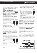
LP GAS ONLY OPERATION

Turn switch "

C

" to the "

ON

" position and press push-

button "

B

". The green indicator lamp over push-button

"

B

" will come on and the refrigerator will operate only on

LP gas even if 120 volts are available. When the vehicle

engine is turned "

OFF

", the AES system initiates a 25

minute delay, preventing the refrigerator from operating

on LP gas.

LP GAS DELAY MODE

When the vehicle engine is turned off, the AES system

initiates a delay cycle which prevents the refrigerator

from operating on LP gas for 25 minutes. The purpose

of the delay is to avoid having a gas flame burning dur-

ing a refueling stop at a gas station (see WARNING).
If the vehicle engine is restarted during this delay pe-

riod, the LP gas operation will not start until the delay

period is over. This means each time the vehicle engine

is stopped, the complete 25 minute delay cycle will take

place. If 120 volt AC becomes available during this de-

lay cycle, the AES system will start operation in the 120

volt AC mode immediately, unless the push-button "B"

(LP gas only) has been pressed.
If the RV is stopped somewhere other than a gas sta-

tion, you may wish to cancel the delay cycle. To do this,

turn the main system switch to "OFF" for several sec-

onds, then turn the main system switch back to "ON"

and the system will immediately start operation in the

LP gas mode.

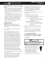
Most LP gas appliances used in recreational ve-

hicles are vented to the outside of the vehicle. When

parked close to a gasoline pump, it is possible that

the gasoline fumes could enter this type of appli-

ance and ignite from the burner flame, CAUSING A

FIRE OR AN EXPLOSION.
FOR YOUR SAFETY, it is recommended that all LP

gas appliances which are vented to the outside

should be shut off when refueling.
The AES system is designed to turn off the LP flame

during refueling stops by the use of the delay cycle

explained previously. However, you must remember

that the delay cycle will be activated only if the

refrigerator is properly connected to the vehicle

engine electrical circuit.
If the refrigerator is not connected to the engine by

the ignition lock wiring, the refrigerator must be

shut off during refueling. To do this, turn the main

system switch "C" to "OFF". Only after the vehicle

has been moved away from the refueling area

should the main system switch "C" be turned back

ON.

SECTION 1

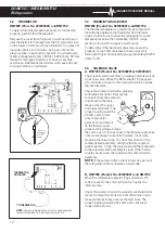
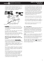
1.1 OPERATION

RM7030 (

Product No. 921890201 & 921890301

)

OFF

ON

AC

A

B

C

D

E

F G

H

All manuals and user guides at all-guides.com

Summary of Contents for RM7030

Page 1: ...ditions Provided is a diagnostic chart leading a qualified mechanic into the service manual pages to locate and solve symptoms which may occur Dometic has continued its commitment in providing service people with this the most up to date information about servicing Dometic RV accessories form No 3 106938 008 2 96 Replaces OS1 684 All manuals and user guides at all guides com a l l g u i d e s c o ...

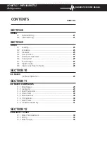
Page 2: ...SECTION 5 DC COMPONENTS 5 1 Thermostat RM7030 Prod No 921890201 921890301 9 5 2 Thermistor RM7030 Prod No 921890401 RM7732 10 5 3 Thermistor Adjuster RM7030 Prod No 921890401 RM7732 10 5 4 Solenoid Valve 10 5 5 Igniter 11 5 6 High Voltage Cable 11 5 7 Fuses 12 5 8 Upper Circuit Board 12 5 9 Lower Circuit Board 15 5 10 Door Switch 17 5 11 Electrode 18 5 12 Climate Control Heater 18 SECTION 6 LP GAS...

Page 3: ... Unit 27 9 7 Food Storage 27 9 8 High Humidity 27 9 9 Interior Liner Seal to Frame 28 SECTION 10 ICE MAKER Ice Maker Operation 29 SECTION11 ICE MAKER COMPONENTS 11 1 Mold Heater 29 11 2 Ice Ejector 29 11 3 Mold Thermostat 29 11 4 Shutoff Arm 30 11 5 Mold Switches 30 11 6 Timing Motor 30 11 7 Water Valve 30 11 8 Ice Maker Assembly 31 SECTION 12 ICE MAKER OTHER 12 1 Water Fill Adjustment 34 12 2 Wir...

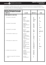
Page 4: ...o 921890201 921890301 SYMPTOM CAUSE REFER TO STEP Operation 1 1 A DC Volts 4 A Fuse 5 7 A Wiring 8 1 8 2 Upper Circuit Board 5 8 A Lower Circuit Board 5 9 A D Operation 1 1 A Thermostat 5 1 Upper Circuit Board 5 8 A Solenoid 5 4 A Wiring 8 2 Lower Circuit Board 5 9 B C D DC Volts 4 A Wiring 8 2 Upper Circuit Board 5 8 B through I Lower Circuit Board 5 9 D Operation 1 1 A AC Volts 2 Heating Element...

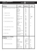
Page 5: ...ltage Cable 5 6 A Electrode 5 11 Wiring 8 2 LP Gas 6 Manual Gas Valve 7 1 Solenoid 5 4 A Orifice 7 2 Burner 7 4 Wiring 8 2 Thermocouple 7 3 A Wiring 8 2 Door Switch 5 10 Door Position 9 4 Food Storage 9 7 Interior Liner to Frame 9 9 High Humidity 9 8 Air Leaks 9 3 Interior Liner to Frame 9 9 High Humidity 9 8 Air Leaks 9 3 Climate Control Heater 5 12 Operation 1 1B or 1 2 DC Volts 4 B Fuse 5 7 B W...

Page 6: ...de 5 11 Solenoid 5 4 B Upper Circuit Board 5 8 J Wiring 8 2 Lower Circuit Board 5 9 E G Ventilation 9 2 Leveling 9 1 Ambient Temperature 9 5 Air Leaks 9 3 Thermistor 5 2 Cooling Unit 9 6 Thermistor Adjuster 5 3 AC Volts 2 Heating Element 3 Lower Circuit Board 5 9 E F LP Gas 6 Orifice 7 2 Flue Baffle 7 5 Flue Tube 7 7 Flue Cap RM7030 Only 7 6 Burner 7 4 Lower Circuit Board 5 9 E G Thermistor 5 2 Th...

Page 7: ...10 Door Position 9 4 Food Storage 9 7 Interior Liner to Frame 9 9 High Humidity 9 8 Air Leaks 9 3 Interior Liner to Frame 9 9 High Humidity 9 8 Air leaks 9 3 Climate Control Heater 5 12 Operation 10 Arm in UP Position 11 4 AC Voltage 2 Water Valve 11 7 Ice Maker Cycle 11 8 Blades frozen in ice 12 1 AC Voltage 2 Water Valve 11 7 Ice Maker Cycle 11 8 Shutoff Arm 11 4 Operation 10 Mold Thermostat 11 ...

Page 8: ...LP GAS DELAY MODE When the vehicle engine is turned off the AES system initiates a delay cycle which prevents the refrigerator from operating on LP gas for 25 minutes The purpose of the delay is to avoid having a gas flame burning dur ing a refueling stop at a gas station see WARNING If the vehicle engine is restarted during this delay pe riod the LP gas operation will not start until the delay pe...

Page 9: ...rator the AES control system is designed to select this mode whenever it is available The only exception to this is when push button B LP gas only mode is selected The 120 volt heating elements attached to the boiler provide the heat necessary to operate the cooling system The thermo stat controls the power ON and OFF to the elements and maintains the desired temperature LOW VOLTAGE MONITOR The AE...

Page 10: ...refrigerator controls both the gas and electric operation thereby eliminating the necessity of resetting each time a different energy source is employed After the initial start up the thermostat should be moved from COLDEST to the desired temperature setting usually about mid setting STANDBY MODE OF OPERATION This control system contains a feature where it will continue to operate the cooling syst...

Page 11: ...mode indica tor lamp C will be illuminated This mode provides LP gas operation only The control system will activate the ignition system and will attempt to light the burner for a period of approximately 45 seconds If unsuccessful the CHECK indicator lamp D will illuminate and the GAS mode indicator lamp C will turn off To restart GAS operation press the main power ON OFF button 1 to the OFF and t...

Page 12: ...d Maximum fuse size 5 amps With the refrigerator operating on AC or gas mode if voltage to the refrigerator slowly drops to or below 9 5 volts DC the gas flame will come on and will not be thermostatically controlled Low DC volts below 9 5 could cause over cooling B RM7030 Prod No 921890401 RM7732 For the refrigerator to operate on any mode DC voltage must be supplied to the terminals at the rear ...

Page 13: ... opera tion DC volts are sent to the solenoid coil which opens the internal valve Check the solenoid coil with a properly calibrated ohm meter Remove the connector from the solenoid and measure the resis tance across the upper and lower terminals The proper reading would be 20 ohms with a toler ance range of ten percent Once flame is lit the thermocouple produces the voltage to keep the valve open...

Page 14: ...If a spark is not produced within 10 seconds the gas flame warning lamp will illumi nate If spark is produced it will take 3 minutes for lamp to illuminate If all of the previous checks are correct the igniter is good do not replace B RM7030 Product No 921890401 and RM7732 The igniter is an electronic device that produces high voltage to create a spark at the burner only on gas mode First verify p...

Page 15: ...ower circuit board With the switch in the ON position CONTINUITY should be indicated be tween the orange terminal to the yellow terminal on the 10 pin connector ORANGE YELLOW 10 PIN CONTINUITY should be indicated between the brown terminal to the red terminal on the 10 pin connector BROWN RED 10 PIN YELLOW GREEN 10 PIN RED BLUE 10 Pin 7 Pin NO continuity should be indicated between the yellow term...

Page 16: ...OVED from the lower circuit board and the ON OFF switch turned to ON BROWN BROWN 10 Pin 7 Pin BLACK BLUE 7 Pin With the gas function switch manually depressed CONTI NUITY should be indicated between the violet terminal on the 10 pin connector to the blue terminal on the 7 pin connector With the gas function switch NOT de pressed A reading wouldNOT be indicated NOTE If the check on gas function swi...

Page 17: ...k on gas mode lamp and switch is not correct verify the wire harness has continuity If wire harness is good replace the upper circuit board YELLOW BROWN 10 Pin 7 Pin BROWN 10 Pin 7 Pin GREEN I GAS FLAME WARNING LAMP NOTE The following checks should be made on the upper circuit board and harness assemblyBEFORE replacing the upper circuit board or wiring harness The checks are to be done with the wi...

Page 18: ...n the lower circuit board The manual test sequence is as follows Position 1 Idle Position all loads off Position 2 Activate AC Heater Check for AC volts at terminals J7 and J8 Position 3 Activate Gas Solenoid Check for DC volts at Gas Solenoid white wire and yellow wire Position 4 Idle position All loads OFF Position 5 Activate spark ignition system Check for DC volts to terminal of igniter and gr...

Page 19: ...tive lead from meter to the blue terminal on the 7 pin connector negative lead from meter A voltage reading indi cates the circuit board is good If no voltage is present replace the circuit board NOTE Before changing the circuit board be sure all troubleshooting steps have been followed BROWN BLUE 10 Pin 7 Pin RM7030 Product No 921890401 RM7732 E DC VOLT ALL TESTS ARE TO BE DONE WITH THE REFRIGERA...

Page 20: ... To check the flame sense circuit of the lower circuit board operate the refrigerator on GAS mode then measure the millivolts between J3 terminal and the other wire connection from the thermocouple The millivolt meter should read between 25 to 35 milli volts with the gas flame burning Next turn the manual shutoff valve to OFF and watch the millivolt reading as it drops Note the millivolt reading w...

Page 21: ...he wires and do a continuity check In the OFF position there should be no continuity In the ON position there should be a continuity reading ELECTRODE TIP 3 16 BURNER To check the heater itself do an ohms resistance reading on the heater wire by using a properly cali brated ohm meter The proper ohms reading is 34 ohms 10 The approximate amp draw is less than 5 1 2 amp NOTE The climate control will...

Page 22: ...utoff valve is where the incoming LP gas supply is attached To check the shutoff valve remove and inspect for any obstructions The valve must be turned to ON before any gas operation can occur MANUAL GAS Shutoff VALVE RM7030 Product No 921890201 921890301 RM7030 Product No 921890401 and RM7732 All manuals and user guides at all guides com ...

Page 23: ...h to the thermocouple Next supply flame to tip of the thermocouple for a few moments while depressing the safety valve Remove the flame and release the safety valve The valve should hold for at least 30 seconds If it does not hold the safety valve open for 30 seconds replace the thermocouple If it does hold for 30 seconds or more the thermocouple is good do not replace it NOTE Be sure the tip on t...

Page 24: ...tube becomes coated with scale or residue from combustion of LP gas the efficiency of gas operation decreases NOTE After cleaning be sure to reinstall the flue baffle and flue cap FLUE CAP FLUE TUBE SECTION 8 WIRING 8 1 EXTERNAL WIRING A 120 Volts AC Connection The refrigerator is equipped with a three prong grounded plug for protection against shock hazards and should be plugged directly into a p...

Page 25: ...22 DOMETIC RM7030 RM7732 Refrigerators DIAGNOSTIC SERVICE MANUAL TYPICAL WIRING DIAGRAM FOR RM7030 PRODUCT NO 921890201 921890301 All manuals and user guides at all guides com ...

Page 26: ...2 2 WHITE YELLOW BLUE T T T 1 120 VOLTS AC A B CIRCUIT BOARD POWER CIRCUIT BOARD DISPLAY D C GAS VALVE THERMISTOR ELECTRODE G THERMOCOUPLE REIGNITER F E K L ABSORPTION UNIT SWITCH TERMINAL BLOCK TERMINAL STRIP I J RETAINER FOR BURNER H N HEATER 120VAC P O FUSE 5A FUSE 3A SWITCH HEATING CABLE R Q M LIGHT U RETAINER FOR TERMINAL BLOCK TERMINAL BLOCK S T CIRCUIT BOARD POWER 5 6 GREY BROWN 7 BLUE GREE...

Page 27: ...24 DOMETIC RM7030 RM7732 Refrigerators DIAGNOSTIC SERVICE MANUAL RM7732 TYPICAL WIRING DIAGRAM All manuals and user guides at all guides com ...

Page 28: ...tion there should be as little open space as possible surrounding the sides and top of the refrigerator to achieve proper air flow All potential dead air pockets should be blocked or baffled to ensure that heat won t be trapped in these spaces and reduce efficiency NOTE Refrigerators should be installed in accordance with appropriate installation instructions received with the refrigerator 9 3 AIR...

Page 29: ...ates as shown in FIG 7 B Secure the refrigerator and the lower front strip with two screws One screw through each hinge See FIG 8 STEP 2 Install the two screws in the top frame A The top decoration panel must be removed from the refrigerator before the screws can be in stalled Open refrigerator door and gently push the tabs out of the hole in the hinge with flat blade screwdriver See FIG 9 FIG 7 F...

Page 30: ...meter in one of the containers of water Next supply 115 volts directly to the AC heating ele ments and operate for at least 12 hours Then check the temperature on the thermometer It should be at 45 degrees or lower depending on test conditions see Sec 9 2 and 9 5 If so the cooling unit is good If the temperature of the water is above 45 degrees replace the cooling unit 9 7 FOOD STORAGE Proper refr...

Page 31: ... the cabinet and slide the refrigerator out approximately 2 4 inches Clean the metal frame and foil backed insulation around the refrigerator Apply a foil backed adhesive tape to the joint between outer frame and foil backed refrigerator insulation Refer to illustration top of page 22 Make sure the refrigerator is dry and that the surface temperatures are above 50 F Use a clear silicon caulking co...

Page 32: ... first container of ice cubes should be dumped if the water system has been winterized or not used for several weeks DOWNPOSITION ICELEVEL BAIL ARM SECTION 11 ICE MAKER COMPONENTS 11 1 MOLD HEATER The mold heater uses 165 watts to thaw the ice free from the mold It is wired in series with the thermostat which also acts as a safety device With power to the appli ance off check for resistance be twe...

Page 33: ...T VIEW MOTOR MOUNTING PLATE TIMING CAM WATER VALVE SWITCH HOLDING SWITCH 11 6 TIMING MOTOR This is a low wattage stall type motor which is geared to the timing cam and ice ejector It is a one RPM motor To check the motor disconnect power to the appliance and test for continuity between the two leads If you DO NOT have continuity replace the motor If you have continuity and the motor runs DO NOT re...

Page 34: ... problem was in the wiring or the unit itself OPERATION While the operation of the ice maker is fairly simple an understanding of its cycle is necessary for the service technician to diagnose specific problems The following series of electrical schematics on the following pages will show a typical cycle and the positions of various components during the cycle the mold and its contents the ejector ...

Page 35: ...32 DOMETIC RM7030 RM7732 Refrigerators DIAGNOSTIC SERVICE MANUAL All manuals and user guides at all guides com ...

Page 36: ...33 DIAGNOSTIC SERVICE MANUAL DOMETIC RM7030 RM7732 Refrigerators All manuals and user guides at all guides com a l l g u i d e s c o m ...

Page 37: ...vel in the appliance Next ensure that the appliance is installed level in the RV If there is still water overflow adjustment of the water fill screw is necessary Locate the screw on the ice maker assembly Turn the screw as necessary toward the or side One full turn of the screw will make an 18cc change in the amount of water DO NOT turn the screw more than one full turn at a time If the water leve...

Page 38: ... water pressure in the water supply line must be between 15 lbs PSI and 125 lbs PSI Lower water pressure water turned off or obstructions or air in the water line can cause low or no ice produc tion First check to see that the water supply is fully turned on Visually check the line for kinks etc which might obstruct the flow of water To remove trapped air loosen the connection at the water solenoi...

Reviews: