background image

7

Information

i

1.7

Declaration of conformity

The current Declaration of Conformity can also
be requested directly from Dometic GmbH,
Siegen.

i

Gene ral

Warranty arrangements are in accordance
with EC Directive 44/1999/CE and the normal
conditions applicable for the country concer-
ned. Please contact your dealer in the event of
a warranty claim.
Any damage due to improper use is not cover-
ed by the warranty. The warranty does not
cover any modifications to the appliance or
the use of 

non-original Dometic parts

. The

warranty does not apply if the installation and
operating instructions are not adhered to and
no liability shall be entertained.

1.5

Warranty 

All information and guidance in these opera-
ting instructions were prepared after taking
into consideration the applicable standards
and regulations as well as the current state of
the art. 

Dometic

reserves the right to make

changes at any time which are deemed to be
in the interest of improving the product and
safety.

1.6

Limitation of liability

Dometic

will assume no liability for damage in

the case of :

n

non-observation of the operating instructi-
ons

n

application not in accordance with the 
regulations or provisions

n

use of non-original spare parts

n

modifications and interferences to the 
appliance

INFORMATION

gives you supplementary and

useful guidance when dealing with your refrige-
rator.

Environmental Tips

ENVIRONMENTAL TIPS 

gives you useful gui-

dance for saving energy and disposal of the
appliance.

289 0318-80_EN_RMF-C_85xx-Installation_N1_Layout 1  10.09.2013  12:48  Seite 7

Summary of Contents for RMF8500

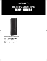
Page 1: ...REFRIGERATION RMF SERIES RMF8500 RMF8501 RMF8505 Absorber refrigerator Installation Manual Absorber K hlschrank Montageanleitung EN DE...

Page 2: ...H Die Dometic Group ist ein kundenorientierter weltweit f hrender Hersteller innovativer Komfortprodukte f r den Wohnwagen Reisemobil Lkw Pkw und Bootsmarkt Die Unternehmensgruppe beliefert dabei eben...

Page 3: ...EN English MBA 07 2013 N 1 Installation instructions Absorption Refrigerator with Refrigerated Drawer for Recreational Vehicles RMF 8500 RMF 8501 RMF 8505...

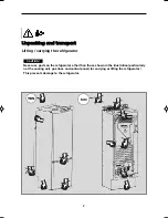
Page 4: ...ing and transport Never use parts on the refrigerator other than those shown in the illustration particularly not the cooling unit gas lines and control panel for carrying or lifting the refrigerator...

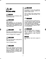
Page 5: ...eakage There is a danger of fire or explosion DANGER It is imperative that the operating pressu re of the pressure reducer on the gas system corresponds to the data specified on the rating plate of th...

Page 6: ...4 Dometic GmbH 2013 Subject to change without prior notice Dometic GmbH In der Steinwiese 16 D 57074 Siegen www dometic com...

Page 7: ...1 Installation 10 4 1 1 Side installation with ventilation grilles 10 4 1 2 Rear installation 11 4 1 3 Installation recess 12 4 1 4 Draught proof installation 12 4 2 Ventilation and air extraction of...

Page 8: ...so they may be referred to at any time 1 2 Guide to these installation instructions The information texts and illustrations in these instructions are copyright protected and are subject to industrial...

Page 9: ...rtained 1 5 Warranty All information and guidance in these opera ting instructions were prepared after taking into consideration the applicable standards and regulations as well as the current state o...

Page 10: ...sional procedures WARNING Never use an unshielded flame to check gas bearing parts and pipes for leakage There is a danger of fire or explosion DANGER Never open the absorber cooling unit It is under...

Page 11: ...n MES 5 automatic and manual energy selection automatic ignition AES Example 2 3 4 5 Refrigerator Mobile Mobile Absorption Refrigerator with refrigerated drawer Model range 8 RM F 8 5 0 1 0 1 5 RMF 85...

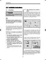
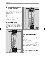
Page 12: ...01 to achieve an optimal cooling performance in high ambient temperatures Fig 2 OK The unit and the exhaust duct system must be in principle installed so that it is accessible for maintenance work ca...

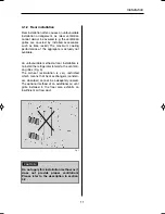
Page 13: ...t available An unfavourable method of rear installation is to install the refrigerator lateral to the ventilati on grilles Fig 5 The air heat recirculation is very restricted which means that heat exc...

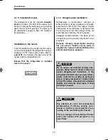
Page 14: ...vice manufacturer s product liability and warranty shall lapse if such materials are used WARNING Installation Pay attention to clean and residue free workmanship if silicone sealing com pound or simi...

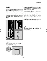
Page 15: ...he outside The draught proof installation does not requi re a special exhaust gas duct to be used Fig 9 Fasten the sealing lips to a stop bar on the rear side 1 e g by gluing Proposal 2 The lip seals...

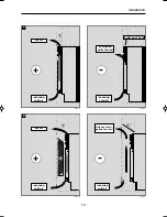
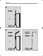
Page 16: ...ney effect 4 2 Ventilation and air extracti on of the refrigerator i Avoid installations marked with the sym bol Good cooling performance is not gua ranteed schematic figures i Heat deflection plate A...

Page 17: ...lation Fig 12 Fig 13 1 hot air incoming cold air incoming cold air 1 Fig 14 2 hot air incoming cold air build up of heat Ventilation grille too low 1 Fig 15 incoming cold air 1 2 Unit heat dissi patio...

Page 18: ...16 Installation Abb 16 3 hot air incoming cold air Abb 17 4 air duct hot air incoming cold air 3 Abb 18 hot air incoming cold air build up of heat...

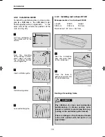
Page 19: ...e ventilation grilles must have an open cross section of at least 400cm This is achieved by using the Dometic LS 300 absor ber ventilation and air extraction system which has been tested and approved...

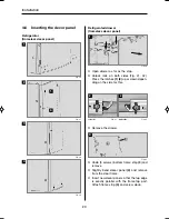
Page 20: ...all of the vehicle for position of the cuts see Fig 22 b a 14 x Fig 30 Seal the installation bays and screw them to the vehicle roof 1 Fig 31 Place the hood in postion and screw it to the installation...

Page 21: ...ust penetrate the casing of the refrigerator Fig 35 In the sidewalls of the refrigerator there are four plastic sleeves for securing the refrigera tor The sidewalls or strips attached for secu ring th...

Page 22: ...th sides Fig 41 42 Press the latches 1 2 up or down depen ding on the side for this n Remove the drawer n Undo 3 screws bottom frame strip 3 and remove n Slightly bend decor panel 4 and remove from th...

Page 23: ...ed by means of Ermeto olive type fitting L8 DIN 2353 ST complying with EN 1949 s figure 44 45 Specialised personnel are accredited experts who are able by virtue of their training and knowledge to vou...

Page 24: ...or by high voltage drop on the cable n Changes to the internal electrical instal lation or the connection of other electri cal components e g external fan to the internal wiring of the appliance will...

Page 25: ...alled in a caravan the respective leads for the 12V and 12V connections A B and C D must not be connected to each other on the caravan side EN 1648 1 CAUTION 4 8 3 D and solar connection only for AES...

Page 26: ...ermanent voltage supply for functional electronics Connections for models RMF 85x0 Connections for models RMF 85x1 MES RMF 85x5 AES Fig 47 A Ground heating element DC brown B Positive connection heati...

Page 27: ...ion 12 V D signal connection S signal connection Heating element mains connection 230 V AC 2 3 4 1 Plug in contacts manufacturer Stocko MF 9562 002 80E MF 9562 002 8 OC 3 pin with D contact MF 9562 00...

Page 28: ...26 Circuit diagram RMF 85x1 RMF 85x5 Fig 51 1 C D B A Installation 4 8 5 Circuit diagrams...

Page 29: ...upply at the terminals C D permanent voltage supply for functional electronics 12V OUT 12 V power supply for optional connections Ground connection heating element 12VDC Positive connection heating el...

Page 30: ...ation Fig 69 Circuit diagram RMF 85x0 A B C D Ground connection heating element 12VDC Positive connection heating element 12VDC Ground connection internal lighting Positive connection internal lightin...

Page 31: ...Einbauanleitung Absorber K hlschrank mit K hlschublade f r Freizeitfahrzeuge DE Deutsch MBA 07 2013 N 1 RMF 8500 RMF 8501 RMF 8505...

Page 32: ...und Transport Nutzen Sie niemals zum Tragen oder Anheben des K hlschranks andere Teile am K hl schrank als die in der Abbildung gezeigten vor allem nicht das Aggregat Gasleitungen und Bedienblende Si...

Page 33: ...Undichtigkeit Es besteht Brand oder Explosionsgefahr GEFAHR Der Betriebsdruck des Druckminderers an der Gasanlage muss unbedingt der Angabe auf dem Typenschild des K hlschranks entsprechen Bei abweich...

Page 34: ...4 Dometic GmbH 2013 nderungen vorbehalten Dometic GmbH In der Steinwiese 16 D 57074 Siegen www dometic com...

Page 35: ...Daten 9 4 0 Einbauanleitung 10 4 1 Einbau 10 4 1 1 Seitlicher Einbau mit L ftungsgittern 10 4 1 2 Heckeinbau 11 4 1 3 Einbaunische 12 4 1 4 Zugdichter Einbau 12 4 2 Be und Entl ftung des K hlschranks...

Page 36: ...nd Abbildungen in dieser Anleitung sind urheberrechtlich gesch tzt und unterliegen den gewerblichen Schutzrechten Kein Teil dieser Anleitung darf ohne die schrift liche Genehmigung der Dometic GmbH Si...

Page 37: ...in dieser Einbau anleitung wurden unter Ber cksichtigung gel tender Normen und Vorschriften sowie dem Stand der Technik erstellt Dometic beh lt sich vor jederzeit nderungen am Produkt vorzunehmen die...

Page 38: ...nd oder Personensch den entstehen WARNUNG berpr fen Sie niemals gasf hrende Teile und Leitungen mit einer offenen Flamme auf Undichtigkeit Es besteht Brand oder Explosionsgefahr GEFAHR ffnen Sie niema...

Page 39: ...uelle Energiewahl automatische Z ndung MES 5 automatische und manuelle Energiewahl automat Z ndung AES Beispiel 3 1 Modellbezeichnung 2 3 4 5 Refrigerator Mobile Mobiler Absorberk hlschrank mit K hlsc...

Page 40: ...Nr 241 2985 01 um eine optimale K hlleistung bei hohen Umgebungstemperaturen zu erreichen Abb 2 OK Das Ger t und die Abgasf hrung m ssen grunds tzlich so eingebaut werden dass es f r Servicearbeiten...

Page 41: ...e ungeeignete Variante des Heckeinbaus ist der Einbau des K hlschranks seitlich zu den L ftungsgittern Abb 5 Die Luft W rme Umw lzung ist sehr eingeschr nkt wodurch die W rmetauscher Kondenser Absorbe...

Page 42: ...zur Abdichtung es besteht Brandgefahr Bei deren Verwendung erlischt die Produkt haftung und Gew hrleistung des Ger teherstellers WARNUNG Einbau Achten Sie auf saubere und r ckstands freie Verarbeitung...

Page 43: ...m Geh use anliegen Der Ausbau des K hlschranks zur Wartung und Reparatur ist so leicht m glich Abb 9 Befestigen Sie die Dichtlippen an einer r ck seitigen Anschlagsleiste 1 z B durch Kleben Vorschlag...

Page 44: ...effekt 4 2 Be und Entl ftung des K hlschranks i Abb 10 Bel ftungsprinzip Beispiel mit L ftungsgittern Abb 11 Bel ftungsprinzip Alternativ Beispiel mit Dachentl fter Vermeiden Sie die mit dem Symbol ge...

Page 45: ...15 Einbau Abb 12 Abb 13 1 Warmluft Kaltluft Kaltluft 1 Abb 14 2 Warmluft Kaltluft W rmestau L ftungsgitter zu tief 1 Abb 15 Kaltluft 1 2 Ableitung der Aggregatw rme zu gering...

Page 46: ...16 Einbau Abb 16 3 Abb 17 4 Luftkanal Warmluft Kaltluft Warmluft Kaltluft 3 Abb 18 Warmluft Kaltluft W rmestau...

Page 47: ...ftungs ffnung Die Bel ftungsgitter m ssen einen freien Querschnitt von mindestens 400 cm auf weisen Dies wird mit dem Dometic Absorber Be und Entl ftungssystem LS 300 erreicht das f r diesen Zweck ge...

Page 48: ...Fahrzeugau en wand angebracht Lage der Ausschnitte siehe Abb 22 b a 14 x Abb 30 Installationrahmen ab dichten und am Fahr zeugdach festschrau ben 1 Abb 31 Haube aufsetzen und am Rahmen fest schrauben...

Page 49: ...K hlschrank in seine endg ltige Lage gebracht ist werden die Schrauben durch das Geh use des K hlschrankes in die Nischenwand geschraubt Abb 34 Abb 35 In den Seitenw nden des K hlschrankes sind vier K...

Page 50: ...e daf r die Riegel 1 2 entsprechend der Seite nach oben oder nach unten n Entnehmen Sie die Schublade n Untere Rahmenleiste 3 l sen 3 Schrauben und entnehmen n Dekorplatte 4 leicht w lben und aus dem...

Page 51: ...1949 siehe Abb 44 45 Autorisierte Fachkr fte sind anerkannte Sachkundige die aufgrund ihrer Ausbildung und Kenntnisse die Gew hr daf r bieten dass die Installation und die Dichtheitspr fung ordnungsg...

Page 52: ...beln zu ver meiden n Ver nderungen an der internen elektri schen Installation oder der Anschluss anderer elektrischer Komponenten z B fremder Zusatzl fter an der internen Verkabelung des Ger tes f hre...

Page 53: ...Bei Installation im Caravan d rfen cara vanseitig die jeweiligen Minus und Plusleitungen der 12V Anschl sse A B und C D nicht miteinander verbunden werden EN 1648 1 VORSICHT 4 8 3 D und Solaranschlus...

Page 54: ...sorgung an den Klemmen C D anzuschlies sen Dauerversorgung f r die Funktions elektronik Anschl sse bei Modellen RMF 85x0 Anschl sse bei Modellen RMF 85x1 MES RMF 85x5 AES Abb 47 A Masse Heizelement D...

Page 55: ...izelement 12V Anschluss Elektronik 12V Anschluss D Signal Anschluss S Signal Heizelement Netz 230V 2 3 4 1 Steckkontakte Hersteller Stocko MF 9562 002 80E MF 9562 002 8 OC 3 polig mit D Kontakt MF 956...

Page 56: ...26 Schaltschema RMF 85x1 RMF 85x5 Abb 51 1 C D B A Einbau 4 8 5 Schaltschemata...

Page 57: ...lich eine 12V DC Dauerversorgung an den Klem men C D anzuschlie en Dauerversorgung f r die Funktionselektronik 12V OUT 12V Versorgung f r optionale Anschl sse Masse Heizelement 12V Plus Heizelement 12...

Page 58: ...28 Einbau Abb 69 Schaltschema RMF 85x0 A B C D Masse Heizelement 12V Plus Heizelement 12V Minus Innenbeleuchtung Plus Innenbeleuchtung A B C D...

Page 59: ...29 Installation...

Page 60: ...90 64 9 622 1573 Mail customerservices dometic co nz NORWAY Dometic Norway AS ster yveien 46 N 3232 Sandefjord 47 33428450 47 33428459 Mail firmapost dometic no POLAND Dometic Poland Sp z o o Ul Pu aw...

Reviews: