11
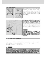
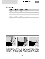
Recess dimensions:
Installation in the recess:
Model Height H
Width B
Depth T
Note: When installing the appliance ensure that
the door hinges are supported.
Figure E24
shows the optimum installation of the refrigera-
tor, whereas
Fig. E25
shows the minimum
requirement with the maximum clearance bet-
ween installation area and end of hinge. If the
installation is carried out as per
Fig. E26
, the
hinge is not capable of supporting the possible
load in the door. It is therefore essential that the
maximum clearance of 1.57
"
not be exceeded.
Ideal fitting
Minimum requirement
Distance not greater than 40mm
RM 8501
RM 8505
RM 8551
RM 8555
RML 8551
RML 8555
32.48
"
32.48
"
32.48
"
32.48
"
49.17
"
49.17
"
20.74
"
20.74
"
20.74
"
20.74
"
20.82
"
20.82
"
21.34
"
21.34
"
23.50
"
23.50
"
23.58
"
23.58
"
THE SIGN OF COMFORT
Fig. E26
Fig. E25
Fig. E24
Summary of Contents for RML 8551
Page 18: ...18 Fig E35 2 0 Tables and wiring diagrams 2 1 Wiring diagrams 2 1 1 Wiring diagram RM 8xx0...
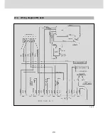
Page 19: ...19 Fig E36 2 1 2 Wiring diagram RM 8xx1 THE SIGN OF COMFORT...
Page 20: ...20 Fig E37 2 1 3 Wiring diagram RM 8xx5...
Page 21: ...21 Fig E38 2 1 4 Wiring diagram RM 8xx5 with electrical doorlock optional THE SIGN OF COMFORT...
Page 23: ...23 THE SIGN OF COMFORT...
Page 24: ......
Page 47: ...23 THE SIGN OF COMFORT...
Page 48: ......

