13
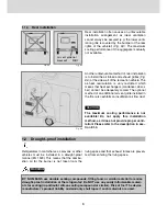
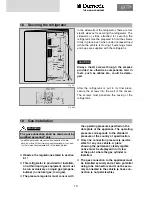
In the sidewalls of the refrigerator, there are four
plastic sleeves for securing the refrigerator. The
sidewalls or strips attached for securing the
refrigerator must be prepared to hold the screws
firmly in place even when under increased load
(while the vehicle is moving). Fastening screws
and caps are supplied with the refrigerator.
Always insert screws through the sleeves
provided as otherwise components laid in
foam, such as cables etc., could be dama-
ged.
After the refrigerator is put in its final place,
secure the screws into the wall of the recess.
The screws must penetrate the casing of the
refrigerator.
1.8
Securing the refrigerator
Fig. E27
Fig. E28
CAUTION
1.9
Gas installation
Observe the regulations stated in section
6.1 !
This refrigerator is provided for installati-
on within liquid gas equipment and must
be run exclusively on liquid gas (propane,
butane) (no natural gas, town gas).
The pressure regulator must concur with
The gas connection shall be carried out by
qualified personnel* only.
WARNING
* qualified personnel are accredited experts who are
able, by virtue of their training and knowledge, to vouch
for the correct implementation of the leakage test.
the operating pressure specified on the
data plate of the appliance. The operating
pressure corresponds to the standard
pressure of the country of specification.
Only one connection pressure is permis
sible for any one vehicle. A plate
showing the permanent, clearly legible
notice must be displayed in full view
at the point where the gas cylinder is
installed.
The gas connection to the appliance must
be installed securely and at zero potential
using tube connectors and must be secu-
rely connected to the vehicle (a hose con-
nection is not permissible).
THE SIGN OF COMFORT
THE SIGN OF COMFORT
Summary of Contents for RML 8551
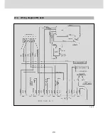
Page 18: ...18 Fig E35 2 0 Tables and wiring diagrams 2 1 Wiring diagrams 2 1 1 Wiring diagram RM 8xx0...
Page 19: ...19 Fig E36 2 1 2 Wiring diagram RM 8xx1 THE SIGN OF COMFORT...
Page 20: ...20 Fig E37 2 1 3 Wiring diagram RM 8xx5...
Page 21: ...21 Fig E38 2 1 4 Wiring diagram RM 8xx5 with electrical doorlock optional THE SIGN OF COMFORT...
Page 23: ...23 THE SIGN OF COMFORT...
Page 24: ......
Page 47: ...23 THE SIGN OF COMFORT...
Page 48: ......

