14
Inflamable material should not be in
immediate proximity to the burner.
The gas connection to the appliance is
effected by means of a suitable coupling
tube fitting.
Hook-up to the gas supply line is accomplished
at the manual gas shutoff valve,
which is furnished with a 3/8" SAE (UNF 5/8" -
18) male flare connection. Always use a backu
wrench when connecting the gas supply line to
the gas inlet fitting.
The gas connection may only be carried
out by a qualified personnel.
Following proper installation, a testing for leaka-
ge and a flame test must be carried out by
*qualified personnel. A certificate of testing must
be issued.
Check all connections for gas leaks with soap
and water.
DO NOT
use a naked flame for
detecting leaks. Ignite the burner to ensure cor-
rect operation of gas valve, burner and ignition.
In case the appliance fails to operate correctly
after all checks have been carried out, refer to
the authorised service provider in your area
A
AT
TT
TE
EN
NT
TIIO
ON
N
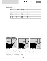
20 Nm
max
15 Nm
max
Test point
Connection
of gas supply
Gas burner
SW 14
SW 17
Gas supply
LP GAS
CYLINDER
PRESSURE
REGULATOR
TO
REFRIGERA-
TOR
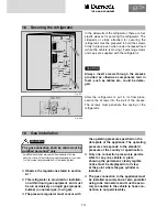
The refrigerator must be equipped with a gas cock
in the supply line to allow the supply to be discon-
nected. Such a cut-out device must be readily
accessible to the user.
The gas supply system must incorporate a pressu-
re regulator to maintain a supply pressure of not
more than 13.5 inches water column, static (no
load).When testing the gas supply system at test
pressures in excess of 1/2 psig, the refrigerator
and its individual shutoff valve must be discon-
nected from the gas supply piping system.When
testing the gas supply system at pressures less
than or equal to 1/2 psig, the appliance must be
isolated from the gas supply piping by closing its
individual manual shutoff valve.In case detailed
instructions on the installation and connection to
the gas supply are required, contact your dealer or
distributor.
Gas pressure
Refer to data label.
Fig. E29
Summary of Contents for RML 8551
Page 18: ...18 Fig E35 2 0 Tables and wiring diagrams 2 1 Wiring diagrams 2 1 1 Wiring diagram RM 8xx0...
Page 19: ...19 Fig E36 2 1 2 Wiring diagram RM 8xx1 THE SIGN OF COMFORT...
Page 20: ...20 Fig E37 2 1 3 Wiring diagram RM 8xx5...
Page 21: ...21 Fig E38 2 1 4 Wiring diagram RM 8xx5 with electrical doorlock optional THE SIGN OF COMFORT...
Page 23: ...23 THE SIGN OF COMFORT...
Page 24: ......
Page 47: ...23 THE SIGN OF COMFORT...
Page 48: ......

