17
S+ - connection :
12V DC
energy can be optionally achieved by
mounting solar equipment to the vehicle. The
solar power equipment must be provided with a
solar charging controller with
AES outpu
t (ade-
quate charging controllers available in selected
stores). The "S+ connection (Solar +) must be
connected to the respective terminal of the solar
charging controller (
AES output
). The electronic
system uses the
S+ signal
of the solar charging
controller to detect
solar 12V DC
.
D+
S+
on the vehicle
on the appliance
Fig. E33
Fig. E34
Cable cross-sectional areas :
Switch-over time within the individual energy modes in automatic mode:
There are no particularly high current flows via
the D+ and S+ connection; therefore no particu-
larly large cross-section is required for these
connections (approx. 0.04
"
² is sufficient).
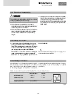
230V
Gas
12V Solar
12V DC
~2-5 s
~2-5 s
~2-5 s
~2-5 s
~2-5 s
~2-5 s
~2-5 s
15 min
~2-5 s
~2-5 s
THE SIGN OF COMFORT
Summary of Contents for RML 8551
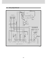
Page 18: ...18 Fig E35 2 0 Tables and wiring diagrams 2 1 Wiring diagrams 2 1 1 Wiring diagram RM 8xx0...
Page 19: ...19 Fig E36 2 1 2 Wiring diagram RM 8xx1 THE SIGN OF COMFORT...
Page 20: ...20 Fig E37 2 1 3 Wiring diagram RM 8xx5...
Page 21: ...21 Fig E38 2 1 4 Wiring diagram RM 8xx5 with electrical doorlock optional THE SIGN OF COMFORT...
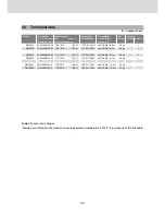
Page 23: ...23 THE SIGN OF COMFORT...
Page 24: ......
Page 47: ...23 THE SIGN OF COMFORT...
Page 48: ......

