4
TJ18, TJ22, TJ42, TJF42 & TJ80 Installation And Operating Instructions
60°C
75°C
80°C
90°C
105°C
125°C
200°C
(140° F)
(167°F)
(176°F)
(194°F)
(221°F)
(257°F)
(392°F)
Outside
Conductor
Outside Inside
Outside Inside
Outside Inside
Outside Inside
Outside Inside
Outside Inside
or inside
Size
Engine Engine
Engine Engine
Engine Engine
Engine Engine
Engine Engine
Engine Engine
Engine
(AWG)
Spaces Spaces
Spaces Spaces
Spaces Spaces
Spaces Spaces
Spaces Spaces
Spaces Spaces
Spaces
18
7.0
4.1
7.0
5.3
10.5
8.2
14.0
11.5
14.0
11.9
17.5
15.6
17.5
16
10.5
6.1
10.5
7.9
14.0
10.9
17.5
14.4
17.5
14.9
21.0
18.7
24.5
14
14.0
8.1
14.0
10.5
17.5
13.7
21.0
17.2
24.5
20.8
28.0
24.9
31.5
12
17.5
10.2
17.5
13.1
24.5
19.1
28.0
23.0
31.5
26.8
35.0
31.2
38.5
10
28.0
16.2
28.0
21.0
35.0
27.3
38.5
31.6
42.0
35.7
49.0
43.6
49.0
8
38.5
22.3
45.5
34.1
49.0
38.2
49.0
40.2
56.0
47.6
63.0
56.1
70.0
6
56.0
32.5
66.5
49.9
70.0
54.6
70.0
57.4
84.0
71.4
87.5
77.9
94.5
4
73.5
42.6
87.5
65.6
91.0
71.0
94.5
77.5
112.0
95.2
119.0
105.9
126.0
3
84.0
48.7
101.5
76.1
105.0
81.9
108.5
89.0
126.0
107.1
136.5
121.5
147.0
2
98.0
56.8
119.0
89.3
122.5
95.6
126.0
103.3
147.0
125.0
157.5
140.2
168.0
1
115.5
67.0
136.5
102.4
147.0
114.7
147.0
120.5
171.5
145.8
185.6
165.1
196.0
0
136.5
79.2
161.0
120.8
171.5
133.8
171.5
140.6
199.5
169.6
213.5
190.0
227.5
00
157.5
91.4
185.5
139.1
199.5
155.6
199.5
163.6
231.0
196.4
248.5
221.2
259.0
000
182.0
105.6
217.0
162.8
31.0
180.2
231.0
189.4
269.5
229.1
287.0
255.4
301.0
0000
210.0
121.8
252.0
189.0
269.5
210.2
269.5
221.0
311.5
264.8
332.5
295.9
357.0
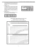
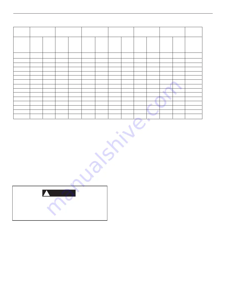
ABYC Standards - ABYC Guidelines E8 - Alternating Current/Amperage
Temperature Rating of Conductor Insulation
(Guidelines when using an AC/DC Converter)
INSTALLATION INSTRUCTIONS
B. Unpacking, Handling, and Inspection In-
structions
This refrigerator contains an exposed coil
assembly. To avoid personal injury, wear pro-
tective gloves when unpacking and handling
refrigerator.
1.
Inspect packaging for transport damage. Note any
packaging damage that may indicate hidden dam-
age to the refrigerator.
2.
Remove refrigerator from packaging.
3.
Inspect refrigerator for damage. Report any dam-
age resulting from transport to the dealer no later
than 24 hours after delivery. A notice is printed on
the top of each box, describing the general proce-
dures required.
4.
Dispose of packaging material in accordance with
local laws for sorted waste recycling.
A. Precautions
1.
Read and understand the Installation and Operat-
ing instructions before attempting to start your re-
frigerator installation.
2.
The manufacturer assumes no responsibility for
any injuries or damage caused by non compliance
with any of the installation instructions.
3.
The refrigerator must be wired and grounded in
accordance with the ABYC Guideline E9 or equiva-
lent. See ABYC Guidelines E9 page 3.
CAUTION
!
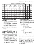
C. Ventilation Requirements
All units require ventilation for proper operation. For
models TJ18, TJ22, TJ42 & TJF42 use a minimum of
50 total square inches of ventilation. For model TJ80
use a minimum of 76 total square inches. Two vents
(inlet/discharge) are recommended. See FIG. 1.
2" clearance at the rear of unit is required.
1.
Approved Vent Locations
a.
TJ18, TJ22, TJ42 & TJF42
(A & C) or (B & D) - Pair Of Grills = 50
Square Inch Minimum
Inlet - 25 Square Inch Minimum
Discharge - 25 Square Inch Minimum
A or B - Single Grill = 50 Square Inch Mini-
mum
b.
TJ80
(E & F) - Pair of Grills = 76 Square Inch
Minimum
Inlet - 38 Square Inch Minimum
Discharge - 38 Square Inch Minimum
G or H - Single Grill = 76 Square Inch Mini-
mum
Note:
For other vent locations contact Dometic Environ-
mental System’s Application Department
D. Electrical Connection
Important:
Route supply wires in a manner that will not
interfere with the placement of the refrigerator. Make sure
the refrigerator is not standing on the power supply cable.
Important:
Before connecting the refrigerator to the 12
VDC power supply, check that the line voltage corresponds
to the indications on the refrigerator rating plate and those
of the compressor plate.


