13
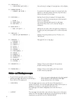
• The following information is stored in the Alarm History :
Temperature alarm :
ALARM :
type of alarm (HIGH ALARM or LOW ALARM)
START :
Start date and time of alarm situation
END :
End date and time of alarm situation
AVG :
Average temperature on the display sensor during the alarm situations.
MAX / MIN :
Maximum or minimum temperature value on the display sensor during the
alarm situation (depending on the type of temperature alarm)
Powerfail alarm :
ALARM :
POWERFAIL
START :
Start date and time of alarm situation
END :
End date and time of alarm situation
AVG :
Average temperature on the display sensor during the alarm situations
• To delete the alarm history, select the function “DELETE HISTORY” from the EXTRA menu.
R
Reecchhaarrggeeaabbllee bbaatttteerryy
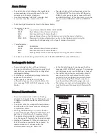
• The monitoring functions of the electronics
during an interruption of the power supply for at
least 48 hours are maintained by an integrated
rechargeable battery.
• This battery is automatically charged when the
appliance is connected.
• If the capacity of the battery is no longer
sufficient to take over the control function, the
error message “BAT.1 LOW/FAIL” appears on the
display.
• At the first starting up it may happen that the
message „BAT.1 LOW/FAIL” appears. The message
will disappear as soon as the battery is charged.
• The battery should be pre-emptively replaced
every 2 years. This replacement must only be
carried out by a recognised service technician.
Before dismantling the battery the appliance
must be switched off and the plug pulled out.
• The battery is a lead-acid storage battery that
must be disposed of separately in the case of a
fault.
E
Exxtteerrnnaall A
Allaarrm
mffuunnccttiioonn
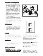
• There are two terminals with three floating
contacts on the back of the unit that can be used
to trigger an additional external alarm (visual or
audible).
• The upper contacts correspond to temperature-
and door-alarm, the lower contacts correspond
to a powerfail-alarm.
• Pressing the ENTER-key in an alarm situation
only switches off the internal audible alarm. The
key does not interfere with the external alarm.
The external alarm signal is only switched off
once the cause of the alarm has been eliminated.
• A voltage of between 12V DC and a maximum of
250V AC can be connected at the contacts. The
maximum load must not exceed 8A. The
minimum power rating is 100mA / 5V.
A
Allaarrm
m H
Hiissttoorryy
• The alarm history list contains all relevant data
on temperature and powerfail events. The list
contains up to 20 alarm situations.
• The status message “HISTORY” indicates that
new entries have been made in the list.
• The alarm history list can be accessed via the
“SHOW HISTORY” function in the EXTRA menu.
Within the list you navigate by means of the UP
and DOWN buttons. The first and last entry in the
list are marked “BEGIN OF LIST” and “END OF
LIST”.
Resting state
Alarm
TTE
EM
MP
PE
ER
RA
ATTU
UR
RE
E--A
ALLA
AR
RM
M
D
DO
OO
OR
R--A
ALLA
AR
RM
M
Resting state
Alarm
P
PO
OW
WE
ER
RFFA
AIILL--A
ALLA
AR
RM
M


