9
C
hilled
W
ater
Pump
The chilled water pump relay shall close if the system is in heat mode or cool mode. The pump will be enabled 5 seconds prior to the
first stage being enabled. Pump will be on for continuous operation when system is enabled
S
ea
Water Pump
The sea water pump will have a selectable operating mode between continuous operation or cycle with compressor operation. The
default configuration is to cycle with the demand.
The sea water pump relay shall close 5 seconds before the compressor starts in heating or cooling modes and will open 5 seconds
after the last compressor cycle is completed. If immersion heating is available and used, the sea water pump will be disabled.
In a multistage configuration the pump outputs can be daisy chained at the back of the unit to supply power to the pumps. Thi s will
allow any stage to supply power to the pumps when being staged on and off and as a redundant control for the pumps.
Cooling Mode
Cooling mode is entered when Cool is selected on the touchscreen or with the display buttons. The system will automatically start cooling
depending on temperature setpoint. The pumps will operate as described in the pump operation section.
o
The board will energize the compressor relay if return water/supply water temperature is above the cooling setpoint and the
staging delay has elapsed.
o
The compressor will continue to run until the cooling setpoint has been reached or an alarm condition exists. A stage will have a
minimum run time of 100 seconds before it can be turned off and a minimum off time of 120 seconds before it can be re-enabled.
This minimum on time is required to ensure that the system is not cycling on and off and not allowing the compressor to properly
warm-up. This ensures proper oil lubrication of the system
o
If the system calls for a stage to be toggled on/off, the next available stage will be used that meets the staging criteria.
o
Load shedding will occur in multistage operation when approaching chilled water setpoint.
o
The reversing valve is toggled to relieve head pressure at the end of a compressor run cycle.
Heating Mode
Reverse Cycle Heating mode is entered when Heat is selected on the touchscreen or with the display buttons. The system will
automatically start heating depending on the temperature setpoint. The pumps will operate as described in the pump operation section.
o
The reversing valve relay will be energized to change the unit to operate in Reverse Cycle Heating mode.
o
The VARC will energize the compressor relay if return/supply water temperature below the programmed heating setpoint and
the staging delay has elapsed. The compressor will continue to run and the reversing valve will remain energized until the
heating setpoint has been reached or an alarm condition exists. As setpoint is reached, the compressor will reduce its speed to
maintain the water temperature. Once it has reached temperature and a hysteresis of 1 degree the unit will turn off the
compressor. Once it has turned off the compressor the reversing valve will de- energize after a 2-second delay.
o
A stage will have a minimum run time of 3 minutes before it can be turned off and a minimum off time of 3 minutes before it
can be re-enabled. If the system calls for a stage to be toggled on/off, the next available stage will be used that meets the
staging criteria.
Electric Heating mode is entered when Electric Heat is selected on the touchscreen or with the display buttons. The system will
automatically start heating depending on the temperature setpoint.
o
The VARC will energize the heater relay if return/supply water temperature is below the programmed setpoint and the staging
delay has elapsed in a multistage configuration.
Summary of Contents for VARC 48
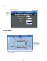
Page 20: ...18 Appendix I Touchscreen Navigation MAIN PAGE Figure 15 CHILLER ENABLE Figure 16...
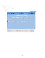
Page 21: ...19 CHILLER SETPOINTS Figure 17...
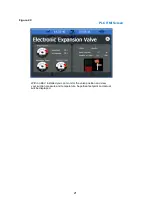
Page 22: ...20 Figure 18 CHILLER STAGE Figure 19...
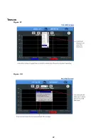
Page 24: ...22 TRENDS Figure 21 Figure 22...
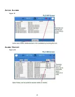
Page 25: ...23 ACTIVE ALARMS Figure 23 ALARM HISTORY Figure 24...
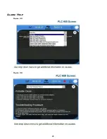
Page 26: ...24 ALARM HELP Figure 25 Figure 26...
Page 27: ...25 REMOTE SUPPORT Figure 27 REMOTE ENABLE Figure 28...
Page 28: ...26 REMOTE CONFIGURATION Figure 29...
Page 41: ...39 Basic wiring diagram...
Page 55: ...53 7 Use Next or Back to scroll to Display Settings 8 Select Display Settings...
Page 69: ...67 VARC Standard Wiring Diagram Figure...
Page 70: ...68 NOTES...
Page 71: ...69 NOTES...


