14
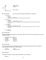
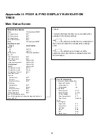
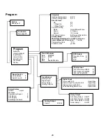
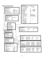
Sub Menu A: Information
o
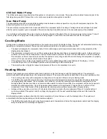
The service contact information is available on this screen.
o
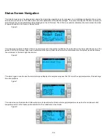
Scroll to view additional firmware information.
o
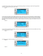
The next screen will contain the flash RAM information.
o
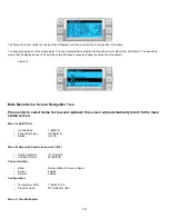
The next screen will contain the power cycle status which indicates how many days the unit has been running in the last
time it was turned off or on.
o
The next screen will contain the Evo firmware information.
o
The next screen will show the power plus firmware information.
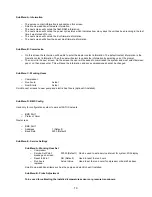
Sub Menu B: Commission
o
On this screen the technician will be able to enter the dealer contact information. The default contact information is the
Dometic contact information. Then the user will select to update the information by selecting yes at the prompt.
o
Then scroll to the next screen. On the screen the user will be asked to commission the system and must select between
yes or no then press enter. This will save the information and once commissioned cannot be changed.
Sub Menu C: Working Hours
o
Compressor
o
Run hours:
Actual
o
Num Starts:
Actual
Scroll to next screens to view pump and electric heat hours (optional if installed).
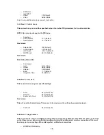
Sub Menu D: BMS Config
Used only for configuration system to work with STIIC network.
o
BMS Port 1
o
Protocol: Carel
Next screen
o
BMS Port 1
o
Adddress
1 (Default)
o
Baud Rate
2400 (Default)
Sub Menu E: Service Settings
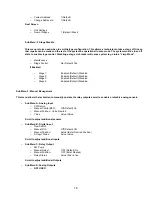
Sub Menu A: Working Hour Set
o
Compressor
o
Service Set Point:
0000h (Default) Can be used to set a service interval for system. Will display
message on screen.
o
Reset to Zero?
NO (Default).
Used to reset the run hours
o
Run hours:
Actual Value.
Used to set the run hours if compressor or board has been
replaced.
Scroll to view additional items such as the pumps and electric heat if installed.
Sub Menu B: Probe Adjustment
To be used for calibrating the installed temperature sensors or pressure transducers.
Summary of Contents for VARC 48
Page 20: ...18 Appendix I Touchscreen Navigation MAIN PAGE Figure 15 CHILLER ENABLE Figure 16...
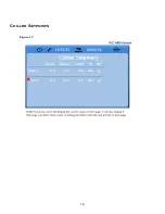
Page 21: ...19 CHILLER SETPOINTS Figure 17...
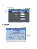
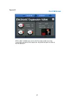
Page 22: ...20 Figure 18 CHILLER STAGE Figure 19...
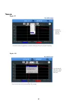
Page 24: ...22 TRENDS Figure 21 Figure 22...
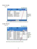
Page 25: ...23 ACTIVE ALARMS Figure 23 ALARM HISTORY Figure 24...
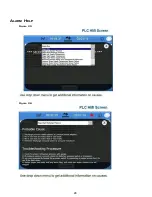
Page 26: ...24 ALARM HELP Figure 25 Figure 26...
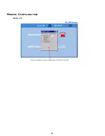
Page 27: ...25 REMOTE SUPPORT Figure 27 REMOTE ENABLE Figure 28...
Page 28: ...26 REMOTE CONFIGURATION Figure 29...
Page 41: ...39 Basic wiring diagram...
Page 55: ...53 7 Use Next or Back to scroll to Display Settings 8 Select Display Settings...
Page 69: ...67 VARC Standard Wiring Diagram Figure...
Page 70: ...68 NOTES...
Page 71: ...69 NOTES...

