16
o
Current Address:
1(Default)
o
Change Address to:
1(Default)
Next Screen
o
Unit Settings
o
Num of Stages
1 (Default) Max 4
Sub Menu: F Stage Disable
This menu is to be used when in a multistage configuration. This allows a technician to take a stage off-line so
that repairs can be made and the rest of the system be operational in auto mode. The system must be in an off
state to enable stage control. Disabling a stage via bre
aker will cause system to go into a “Limp Mode”.
o
Maintenance
o
Stage Control:
No (Default) Yes.
If Enabled,
o
Stage 1:
Enabled (Default) Disabled
o
Stage 2:
Enabled (Default) Disabled
o
Stage 3:
Enabled (Default) Disabled
o
Stage 4:
Enabled (Default) Disabled
Sub Menu F: Manual Management
This menu allows the technician to manually operate the relay outputs as well as enable or disable analog sensors.
o
Sub Menu A: Analog Input
o
CW Return
o
Manual Control B001:
Off (Default) On
o
Manual Position: Value Desired
o
Value:
Actual Value
Scroll to adjust additional sensors
o
Sub Menu B: Digital Input
o
Flow Switch
o
Manual DI 3:
Off (Default) ON
o
Manual Position:
Actual (Enter Desired Position)
o
DI Input Status:
Actual Value
Scroll to adjust additional inputs
o
Sub Menu C: Relay Output
o
SW Pump
o
Manual Relay 1:
OFF (Default) No
o
Manual Position:
OFF (Enter Desired)
o
Relay Status:
Actual Posi in tion
Scroll to adjust additional Outputs
o
Sub Menu D:Analog Outputs
o
NOT USED
Summary of Contents for VARC 48
Page 20: ...18 Appendix I Touchscreen Navigation MAIN PAGE Figure 15 CHILLER ENABLE Figure 16...
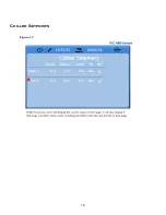
Page 21: ...19 CHILLER SETPOINTS Figure 17...
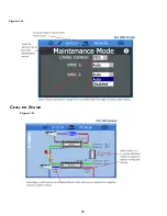
Page 22: ...20 Figure 18 CHILLER STAGE Figure 19...
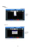
Page 24: ...22 TRENDS Figure 21 Figure 22...
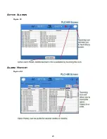
Page 25: ...23 ACTIVE ALARMS Figure 23 ALARM HISTORY Figure 24...
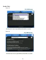
Page 26: ...24 ALARM HELP Figure 25 Figure 26...
Page 27: ...25 REMOTE SUPPORT Figure 27 REMOTE ENABLE Figure 28...
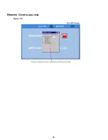
Page 28: ...26 REMOTE CONFIGURATION Figure 29...
Page 41: ...39 Basic wiring diagram...
Page 55: ...53 7 Use Next or Back to scroll to Display Settings 8 Select Display Settings...
Page 69: ...67 VARC Standard Wiring Diagram Figure...
Page 70: ...68 NOTES...
Page 71: ...69 NOTES...

