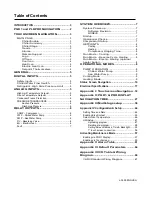
Table of Contents
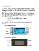
INTRODUCTION .................................................... 3
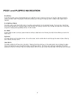
PGD1 and PLDPRO NAVIGATION ............ 2
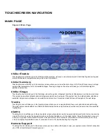
TOUCHSCREEN NAVIGATION .................. 3
MAIN PAGE .......................................................... 3
Chiller Enable ................................................ 3
Chiller Summary ........................................... 3
Chiller Stage ................................................... 3
Trends .............................................................. 3
Alarms .............................................................. 3
Remote Support ............................................ 3
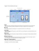
Logo .................................................................. 4
Off Icon............................................................. 4
Cool Icon ......................................................... 4
Heat Icon ......................................................... 4
Electric Heat Icon ......................................... 4
Setpoint Thermometers ............................. 4
GENERAL ........................................................... 5
DIGITAL INPUTS ............................................. 5
Safety Inputs ........................................................... 5
Chilled Water Flow Switch ................................ 5
Refrigerant High Side Pressure Limit .......... 5
ANALOG INPUTS ............................................ 5
High Limit Temperature Setpoint ................................ 5
Freeze Temperature Setpoint ..................................... 6
Condenser Freeze Protection ..................................... 6
PRESSURE TRANSDUCERS .................................... 6
Suction Pressure ................................................ 6
Discharge Pressure ............................................ 6
RELAY OUTPUTS ............................................ 6
COMP
– Compressor ................................................. 6
CWP
– Chilled Water Pump ....................................... 6
SWP
– Sea Water Pump ............................................ 6
RV
– Reversing Valve ................................................. 6
EH
– Electric Heat ...................................................... 6
Fault ............................................................................ 7
SYSTEM OVERVIEW ...................................... 7
System Power-up ................................................ 7
Software Revision ......................................... 7
MODBUS ............................................................ 7
Startup ...................................................................... 7
Operational Checks.............................................. 7
Compressor Startup ............................................. 7
SETPOINTS ........................................................... 8
Cooling ................................................................ 8
Heating ............................................................... 8
Compressor Staging Time ........................ 8
Run Mode
– Cooling ........................................... 8
Run Mode
– Reverse Cycle Heating ............ 8
Run Mode
– Electric Heating (optional
heater barrel).......................................................... 8
OPERATIONAL MODES ............................... 8
PUMP OPERATION ........................................... 8
Chilled Water Pump .................................... 9
Sea Water Pump ............................................ 9
Cooling Mode ......................................................... 9
Heating Mode ........................................................ 9
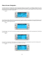
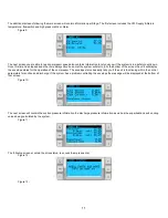
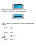
Status Screen Navigation ................................... 10
Electrical Specifications ..................................... 17
Appendix I: Touchscreen Navigation .. 18
Appendix II: PGD1 & PRO DISPLAY
NAVIGATION TREE ...................................... 27
Appendix III Multistage setup ................. 38
Appendix IV Configuration & Setup .................. 44
Setting Time and Date .............................................. 44
Enabling Electric Heat ............................................... 45
Select Unit of Temperature ....................................... 46
HMI Setup ................................................................. 47
Uploading program ........................................... 47
Deleting old program: ........................................ 48
Setting Screen Address, Time & Backlight: ...... 50
7” touch screen connection ............................... 56
Activating Maintenance Mode ........................... 57
Enabling via PGD1 Display ....................................... 57
Enabling via Touchscreen ......................................... 59
Appendix V Alarm Table ............................ 61
Appendix VI Default Parameters ........... 64
Appendix VII I/O Table & Wiring
Diagram ............................................................. 66
VARC Standard Wiring Diagram .................... 67
L-3499 ENGLISH
Summary of Contents for VARC 48
Page 20: ...18 Appendix I Touchscreen Navigation MAIN PAGE Figure 15 CHILLER ENABLE Figure 16...
Page 21: ...19 CHILLER SETPOINTS Figure 17...
Page 22: ...20 Figure 18 CHILLER STAGE Figure 19...
Page 24: ...22 TRENDS Figure 21 Figure 22...
Page 25: ...23 ACTIVE ALARMS Figure 23 ALARM HISTORY Figure 24...
Page 26: ...24 ALARM HELP Figure 25 Figure 26...
Page 27: ...25 REMOTE SUPPORT Figure 27 REMOTE ENABLE Figure 28...
Page 28: ...26 REMOTE CONFIGURATION Figure 29...
Page 41: ...39 Basic wiring diagram...
Page 55: ...53 7 Use Next or Back to scroll to Display Settings 8 Select Display Settings...
Page 69: ...67 VARC Standard Wiring Diagram Figure...
Page 70: ...68 NOTES...
Page 71: ...69 NOTES...


