27
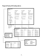
Appendix II: PGD1 & PRO DISPLAY NAVIGATION
TREE
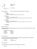
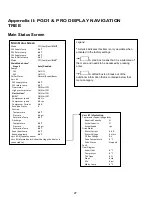
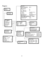
Main Status Screen
Main Status Screen
Mode
Off/Cool/Heat/
El Ht*
CW Supply Temp
#.#°F
CW Return temp
#.#°F
CW Supply temp
#.#°F
Cond. Outlet temp
#.#°F
Mode
Off/Cool/Heat/
El Ht*
Main Mode Active*
Stage #
Auto/Disabled
Pumps
CW
On/Off
SW
On/Off
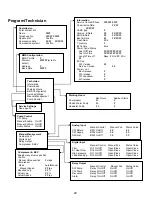
Chiller Status
Normal/Econo/Boost
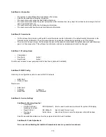
Varc #1
CW supply temp
#.#°F
CW return temp
#.#°F
Flow status
Ok/Alm/Off
High pressure status
Ok/Alm/Off
Electric Heat*
Ok/Alm/Off
EH FL*
Ok/Alm/Off
Compressor speed
#.# Hz
Compressor speed
#.# rps
Compressor Current
#.# A
Envelope Status
#
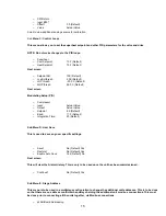
Suction
Temperature
#.#°F
Pressure
#.# psi
Saturation Temp.
#.#°F
Discharge
Temperature
#.#°F
Pressure
#.# psi
Saturation Temp.
#.#°F
Super heat temp
#.#°F
Subcooling temp
#.#°F
Varc #2-4 (repeat as above)
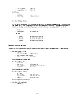
Varc #1 information (will show the stage the display is
connected to)
Varc # 1 Information
Compressor Capacity Regulator
Required Capacity
%
Actual Capacity
%
Actual Speed
rps
Drive Status
Motor Current
#.# A
Motor Voltage
# Vrms
DC Bus Voltage
# V
Drive Temperature
# °F
Drive Status
Stopped
Fault
Flow Diagram
Super Heat
# °F
Compressor
# °F
TXV Open
# %
Steps
# stp
EEV
# psi
Std-by temp
# °F
Legend
*
Asterisk indicates this item is only viewable when
activated in the factory settings.
A solid box means that it is a submenu of
the menu and needs to be accessed by pressing
enter.
A dotted box is a break out of the
additional information that is contained below that
menu category.
Summary of Contents for VARC 48
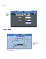
Page 20: ...18 Appendix I Touchscreen Navigation MAIN PAGE Figure 15 CHILLER ENABLE Figure 16...
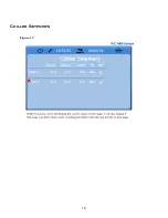
Page 21: ...19 CHILLER SETPOINTS Figure 17...
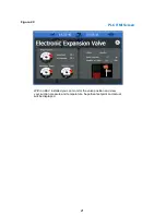
Page 22: ...20 Figure 18 CHILLER STAGE Figure 19...
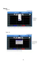
Page 24: ...22 TRENDS Figure 21 Figure 22...
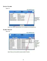
Page 25: ...23 ACTIVE ALARMS Figure 23 ALARM HISTORY Figure 24...
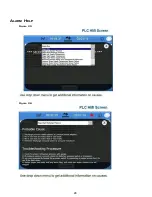
Page 26: ...24 ALARM HELP Figure 25 Figure 26...
Page 27: ...25 REMOTE SUPPORT Figure 27 REMOTE ENABLE Figure 28...
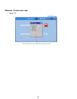
Page 28: ...26 REMOTE CONFIGURATION Figure 29...
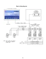
Page 41: ...39 Basic wiring diagram...
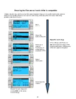
Page 55: ...53 7 Use Next or Back to scroll to Display Settings 8 Select Display Settings...
Page 69: ...67 VARC Standard Wiring Diagram Figure...
Page 70: ...68 NOTES...
Page 71: ...69 NOTES...

