28
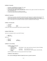
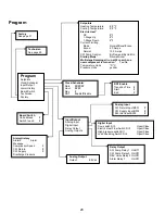
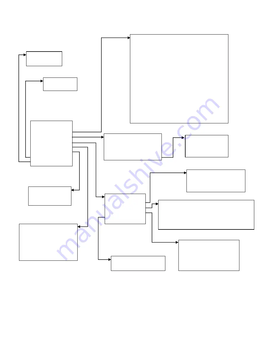
Program
Program
Setpoints
Clock/Scheduler
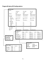
Input/Output
Alarm History
Board Switch
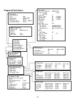
Technician
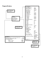
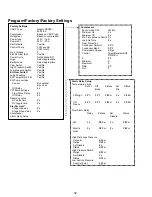
Factory
Analog Output
Output
#.# Vdc
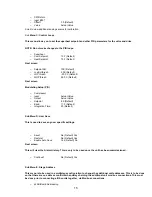
Setpoints
Heating Temperature
#.# °F
Cooling Temperature
#.# °F
Electric Heat*
SP
#°F
1-Stage Up
#°F
1-Stage Down
#°F
Current Limiting
Mode
Normal/Boost/Econo
Econo
4.0 Amps
Normal
10.0 Amps
SW Pump Control
By Demand/By Unit On
Startup Mode*
Normal/Accel
Multistage Ramping all run at 50 rps when a
new compressor is turned on*
Yes/No
Temperature Units
°F/°C
Pressure Units
psi/bar
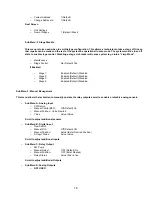
Clock/Scheduler
Date
##/##/##
Hour
##:##
Day
#
DST
Enable/Disable
DST Enable
Transition Time #
Start
#
End
#
Input/Output
Analog Input
Digital Input
Relay Output
Analog Outputs
Analog Input
CW Return Input B001
#
CW Supply Input B002
#
SW Inlet Input B003
#
Digital Input
Flow switch DI 3
Open/Close
Electric Heat Flow Switch DI 5
Open/Close
High pressure switch DI 1
Open/Close
Load Shedding Switch DI 4
Open/Close
Relay Output
SW Pump Relay 1 On/Off
CW Pump Relay 2 On/Off
REV Valve Relay 3 On/Off
Alarm Relay 7
On/Off
Board Switch
Unit address:
#
Switch to unit:
#
Factory
See page 31
Technician
See page 29
Alarm History
Alarm# Alarm
Message
Compressor Speed
#
CW Return
#
CW Supply
#
Discharge Pressure
#
Summary of Contents for VARC 48
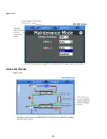
Page 20: ...18 Appendix I Touchscreen Navigation MAIN PAGE Figure 15 CHILLER ENABLE Figure 16...
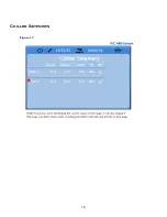
Page 21: ...19 CHILLER SETPOINTS Figure 17...
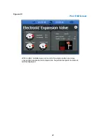
Page 22: ...20 Figure 18 CHILLER STAGE Figure 19...
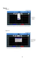
Page 24: ...22 TRENDS Figure 21 Figure 22...
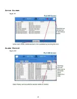
Page 25: ...23 ACTIVE ALARMS Figure 23 ALARM HISTORY Figure 24...
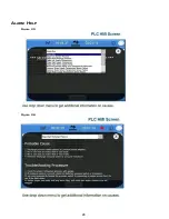
Page 26: ...24 ALARM HELP Figure 25 Figure 26...
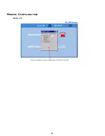
Page 27: ...25 REMOTE SUPPORT Figure 27 REMOTE ENABLE Figure 28...
Page 28: ...26 REMOTE CONFIGURATION Figure 29...
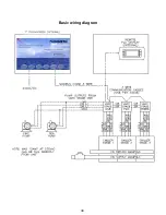
Page 41: ...39 Basic wiring diagram...
Page 55: ...53 7 Use Next or Back to scroll to Display Settings 8 Select Display Settings...
Page 69: ...67 VARC Standard Wiring Diagram Figure...
Page 70: ...68 NOTES...
Page 71: ...69 NOTES...

