38
Appendix III Multistage setup
The VARC can be supplied as a standalone chiller or it can be supplied as part of a staged system.
The factory default setting is set as a standalone chiller.
When supplied as part of a modular system the following connections need to be configured.
o
CW & SW connections between each stage.
o
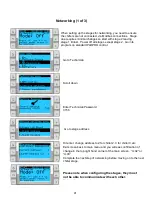
Network connections between each stage. Physical and network addressing.
o
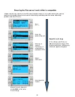
Ensuring Firmware is identical between each stage.
o
Remote control panel configuration.
This document aims to cover all of the above and to run through setting the time, date and unit of
measurement as well as the Boat builder logo (touch screen control only)
Chillers supplied on a frame package will be configured and wired as part of the build process.
Please also note that as part of a correctly configured multistage system there is no need to set
differential/hysteresis settings
.
Initial Wiring
Seawater and chilled water pumps are
wired directly to VARC 1 with no need
for pump relays.
These are connected to the terminals
on the front of chiller 1, remove power
cover and connect as per labelled
connections.
Each chiller stage requires a connection
to the seawater and chilled water pump.
Three core electrical cable needs to link
chiller 1 to chiller 2, chiller 2 to chiller 3
etc for both the seawater and CW
connections
Network connections also need to be
wired from the Network connection
ports. Chiller 1 to Chiller 2, Chiller 2 to
Chiller 3 etc
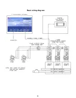
Please refer to the basic wiring diagram
on the next page for clarification
Please refer to the basic wiring diagram on the next page for clarification
Electrical Connections
Summary of Contents for VARC 48
Page 20: ...18 Appendix I Touchscreen Navigation MAIN PAGE Figure 15 CHILLER ENABLE Figure 16...
Page 21: ...19 CHILLER SETPOINTS Figure 17...
Page 22: ...20 Figure 18 CHILLER STAGE Figure 19...
Page 24: ...22 TRENDS Figure 21 Figure 22...
Page 25: ...23 ACTIVE ALARMS Figure 23 ALARM HISTORY Figure 24...
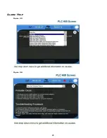
Page 26: ...24 ALARM HELP Figure 25 Figure 26...
Page 27: ...25 REMOTE SUPPORT Figure 27 REMOTE ENABLE Figure 28...
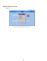
Page 28: ...26 REMOTE CONFIGURATION Figure 29...
Page 41: ...39 Basic wiring diagram...
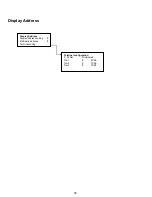
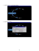
Page 55: ...53 7 Use Next or Back to scroll to Display Settings 8 Select Display Settings...
Page 69: ...67 VARC Standard Wiring Diagram Figure...
Page 70: ...68 NOTES...
Page 71: ...69 NOTES...

