4
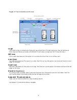
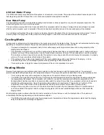
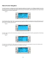
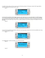
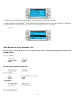
Figure 4: Touch Locations on Screen
L
ogo
The touchscreen logo is customizable. Pressing the logo will return you to the Main menu screen from any sub-screens.
Some screens contain pop-up screens with information. To exit a pop-up, simply touch the X to close the screen.
Off Icon
Off icon will be illuminated only if the system is in a run state. Touch the Off icon to turn off the system.
C
ool Icon
Cool will be illuminated only if the system is in cooling. Touch this icon to put the system in cool mode and the word cool will
appear on the screen.
H
eat Icon
Heat will be illuminated only if the system is in heating. Touch this icon to put the system in heat mode and the word heat will
appear on the screen.
E
lectric
Heat
Icon
Only visible if option is installed. Electric Heat will be illuminated only if the system has electric heat enabled. Touch this
icon to put the system in heat mode and the word heat will appear on the screen.
S
etpoint Thermometers
These icons are touched to adjust the cooling or heating set points.
See Appendix 1 for complete touchscreen navigation.
Summary of Contents for VARC 48
Page 20: ...18 Appendix I Touchscreen Navigation MAIN PAGE Figure 15 CHILLER ENABLE Figure 16...
Page 21: ...19 CHILLER SETPOINTS Figure 17...
Page 22: ...20 Figure 18 CHILLER STAGE Figure 19...
Page 24: ...22 TRENDS Figure 21 Figure 22...
Page 25: ...23 ACTIVE ALARMS Figure 23 ALARM HISTORY Figure 24...
Page 26: ...24 ALARM HELP Figure 25 Figure 26...
Page 27: ...25 REMOTE SUPPORT Figure 27 REMOTE ENABLE Figure 28...
Page 28: ...26 REMOTE CONFIGURATION Figure 29...
Page 41: ...39 Basic wiring diagram...
Page 55: ...53 7 Use Next or Back to scroll to Display Settings 8 Select Display Settings...
Page 69: ...67 VARC Standard Wiring Diagram Figure...
Page 70: ...68 NOTES...
Page 71: ...69 NOTES...


