65
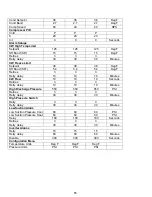
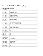
Cond Setpoint
36
36
36
Deg F
Cond Band
2.7
2.7
2.7
Deg F
Comp Speed
60
40
40
RPS
Compressor PID
Cntrl
P
P
P
K
20
20
20
Int
0
0
0
Seconds
Alarm Setups
CW High Temp Limit
Setpoint
125
125
125
Deg F
Off Band (SP-)
15
15
15
Deg F
Retries
3
3
3
Retry delay
30
30
30
Minutes
CW Freeze Limit
Setpoint
38
38
38
Deg F
Off Band (SP+)
5.4
5.4
5.4
Deg F
Retries
3
3
3
Retry delay
10
10
10
Minutes
CW Flow
10
10
10
Seconds
Retries
3
3
3
Retry delay
10
10
10
Minutes
High Discharge Pressure
550
550
550
PSI
Retries
3
3
3
Retry delay
30
30
30
Minutes
High Pressure Switch
Retry
3
3
3
Retry delay
30
30
30
Minutes
Low Suction Alarm
Low Suction Pressure Cool
60
60
60
PSI
Low Suction Pressure Heat
60
60
60
PSI
Delay
180
180
180
Seconds
Retries
3
3
3
Retry delay
30
30
30
Minutes
Inverter Alarms
Retry
15
15
15
Retry delay
60
60
60
Minutes
Disable
300
300
300
Seconds
Configuration Menu
Temperature Units
Deg F
Deg F
Deg F
Pressure Units
PSI
PSI
PSI
Summary of Contents for VARC 48
Page 20: ...18 Appendix I Touchscreen Navigation MAIN PAGE Figure 15 CHILLER ENABLE Figure 16...
Page 21: ...19 CHILLER SETPOINTS Figure 17...
Page 22: ...20 Figure 18 CHILLER STAGE Figure 19...
Page 24: ...22 TRENDS Figure 21 Figure 22...
Page 25: ...23 ACTIVE ALARMS Figure 23 ALARM HISTORY Figure 24...
Page 26: ...24 ALARM HELP Figure 25 Figure 26...
Page 27: ...25 REMOTE SUPPORT Figure 27 REMOTE ENABLE Figure 28...
Page 28: ...26 REMOTE CONFIGURATION Figure 29...
Page 41: ...39 Basic wiring diagram...
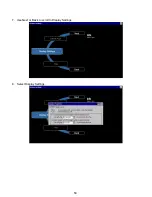
Page 55: ...53 7 Use Next or Back to scroll to Display Settings 8 Select Display Settings...
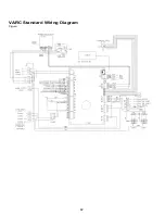
Page 69: ...67 VARC Standard Wiring Diagram Figure...
Page 70: ...68 NOTES...
Page 71: ...69 NOTES...

