66
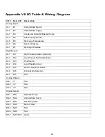
Appendix VII I/O Table & Wiring Diagram
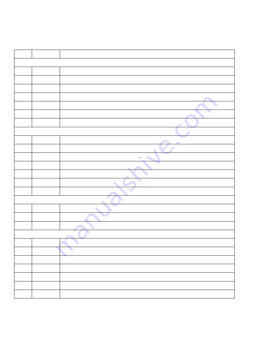
I/O #
Board I/O
Description
Analog Inputs
AI-1
B1
Chilled Water Return
AI-2
B2
Chilled Water Supply
AI-3
B3
Condenser Outlet Refrigerant Temp
AI-4
B4
Suction Temperature
AI-5
B5
Discharge Temperature
AI-6
B6
Suction Pressure
AI-7
B7
Discharge Pressure
Digital Inputs
DI-1
DI1
High Pressure Switch (Optional)
DI-2
DI2
Low Pressure Switch (Optional)
DI-3
DI3
Flow Switch
DI-4
DI4
Load Shedding Input
DI-5
DI5
Electric Heat Flow Switch
DI-6
DI6
Econo Mode Selection
DI-7
DI7
N/A
Analog Outputs
AO-1
Y1
N/A
AO-2
Y2
N/A
AO-3
Y3
N/A
Digital Outputs
DO-1
NO1
Seawater Pump
DO-2
NO2
Chilled Water Pump
DO-3
NO3
Reversing Valve
DO-4
NO4
Electric Heat
DO-5
NO5
N/A
DO-6
NO6
N/A
DO-7
NO7/NC7
Alarm
Summary of Contents for VARC 48
Page 20: ...18 Appendix I Touchscreen Navigation MAIN PAGE Figure 15 CHILLER ENABLE Figure 16...
Page 21: ...19 CHILLER SETPOINTS Figure 17...
Page 22: ...20 Figure 18 CHILLER STAGE Figure 19...
Page 24: ...22 TRENDS Figure 21 Figure 22...
Page 25: ...23 ACTIVE ALARMS Figure 23 ALARM HISTORY Figure 24...
Page 26: ...24 ALARM HELP Figure 25 Figure 26...
Page 27: ...25 REMOTE SUPPORT Figure 27 REMOTE ENABLE Figure 28...
Page 28: ...26 REMOTE CONFIGURATION Figure 29...
Page 41: ...39 Basic wiring diagram...
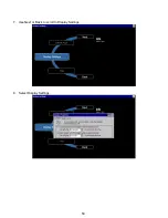
Page 55: ...53 7 Use Next or Back to scroll to Display Settings 8 Select Display Settings...
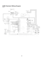
Page 69: ...67 VARC Standard Wiring Diagram Figure...
Page 70: ...68 NOTES...
Page 71: ...69 NOTES...

