CAM29
Installing the reversing video camera
EN
19
I
➤
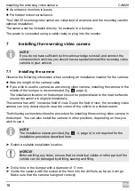
Check that the camera is installed securely.
It must be firmly seated and may not fall out of the drill holes due to vibrations.
7.2
Laying cables
A
I
Therefore, please observe the following instructions:
Wherever possible, lay cables inside the vehicle, as they are better protected there
than outside.
If you do need to lay a cable outside the vehicle, ensure that it is well fastened (use
additional cable ties, insulating tape etc.).
To prevent damage to the cables when laying them, ensure that they are far enough
away from hot or moving vehicle components (exhaust pipes, drive shafts, light sys-
tems, fans, heaters, etc.).
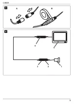
Wrap good-quality insulating tape around the plug connections of the connecting
cables and every connection on a cable (including inside the vehicle) to ensure no
water can penetrate them (fig.
5
page 5). The most suitable tape for this is self-vul-
canising tape, e.g. made by 3M.
When laying the cables, make sure:
– They are not kinked or twisted
– They do not rub on edges
– They are not laid in sharp-edged ducts without protection (fig.
2
, page 3).
Attach the cables securely in the vehicle with cable binders, insulating tape or by glue-
ing them to prevent them from being tripped over.
NOTE
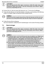
Make sure it is correctly aligned. If the camera is not correctly aligned, the pic-
ture will be askew or upside down on the monitor.
NOTICE!
Before drilling any holes, ensure that no electrical cables or other parts of the
vehicle can be damaged by drilling, sawing and filing.
NOTE
As far as possible, use original ducts for laying the cables, or other suitable
options such as panelling edges, ventilation grilles or dummy plugs. If there
is no rubber plug, produce a suitable hole with a diameter of around 13 mm
and insert a cable bushing sleeve.
Cables and connections that are not properly installed will cause malfunc-
tions or damage to components. Correct installation of cables and connec-
tions ensures lasting and trouble-free operation of the retrofitted
components.
Summary of Contents for Waeco PerfectView CAM29
Page 4: ...CAM29 3 1 2 ...
Page 5: ...CAM29 4 1 3 2 3 17 mm 1 4 ...
Page 6: ...CAM29 5 A B 5 5 1 3 2 4 6 ...

