EN
25
4 Oxygen Analyser
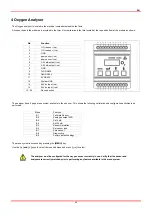
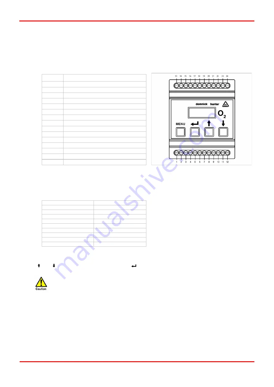
The Oxygen analyser is located in the electrical compartment behind the facia.
All connections to the module are provided in the form of screw terminals that are located at the top and bottom of the module as shown.
Pin Function
1 %
O
2
sensor (-ve)
2 %
O
2
sensor (+ve)
3 GND
4
ppm sensor (-ve)
5
ppm sensor (+ve)
6
4-20 mA output (+ve)
7
4-20 mA output (-ve)
8 GND
9 TxD
RS232
10 RxD
RS232
11 0V
RS232
12 System
GND
13
24V dc input (-ve)
14
24V dc input (+ve)
15 - 24
No connection
The analyser has a 9 page menu system available to the end user. This allows the following calibration and configuration activities to be
performed
Menu Function
E:1 Calibrate
Sensor
E:2 Analogue
output
FSD
E:3
Set 4 mA
E:4
Set 20 mA
E:5 Sensor
simulation
E:6
Set sensor type
E:7 Zero
sensor
E:8 Diagnostics
E:9
Factory default settings
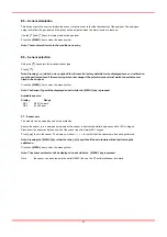
The menu system is accessed by pressing the
[MENU]
key.
Use the
[ ] and [ ]
keys to select the required menu and press
[
]
to select.
The analyser must be configured for the oxygen sensor currently in use. Verify that the sensor and
analyser are correctly matched prior to performing any feature available in the menu system.
Summary of Contents for Maxigas 104
Page 1: ...104 120 SERVICE GUIDE ...
Page 2: ......
Page 4: ......
Page 8: ......
Page 10: ...10 Menu Map ...
Page 11: ...11 ...
Page 14: ......
Page 30: ......
Page 32: ......
Page 33: ...EN 33 APPENDIX A SCHEMATICS ...
Page 34: ......
Page 35: ......


