27
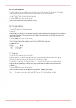
E5 – Sensor simulation
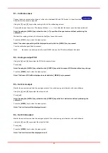
This option allows the user to simulate the sensor output in order to test the functionality of the analyser. The analogue
output will reflect the gas level and the relays will be activated when the alarm levels are reached.
Use the
[ ]
and
[ ]
keys to display the desired gas level.
Press the
[ MENU ]
key to close the menu system.
Note: The module will return to the conditions on entry.
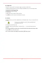
E6 – Sensor selection
Using the
[ ]
key select the required sensor type.
Press
[
]
.
Note: Pressing
[
]
whilst in menu option E:8 will reset the factory defaults for the displayed sensor. A calibration
must be performed even if the sensor type was not changed. The selected sensor must match the actual sensor
fitted to the analyser.
Press the
[ MENU ]
key to close the menu system.
Note: The Sensor Type will be displayed on exit while the
[ MENU ]
key is pressed.
Available sensors:
Display
Range
O2-1
0-25% Volume
O2-2
0-1000 ppm
E7 – Sensor zero
The module can be zeroed by one of two methods.
Ensure the sensor is in a zero-gas environment, the sensor is best zeroed whilst being exposed to 100% nitrogen.
Disconnect the sensor and place a short at the sensor input to simulate 0% oxygen.
Press
[
]
to zero the sensor. The display will show ‘
– – – –
‘ to confirm that the sensor zero has been performed.
Note: Pressing the [ MENU ] key rather than the
[
]
key will exit the zero feature without performing the
calibration.
Press the
[ MENU ]
key to close the menu system.
Note: The sensor zero factor will be displayed on exit while the
[ MENU ]
key is pressed.
Note:
the sensor can be zeroed via the serial RS232 link, see the PC software Manual for details.
Summary of Contents for Maxigas 104
Page 1: ...104 120 SERVICE GUIDE ...
Page 2: ......
Page 4: ......
Page 8: ......
Page 10: ...10 Menu Map ...
Page 11: ...11 ...
Page 14: ......
Page 30: ......
Page 32: ......
Page 33: ...EN 33 APPENDIX A SCHEMATICS ...
Page 34: ......
Page 35: ......


