Manuale HL.ACFP - Ver. 19.09
Pag.
21
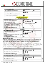
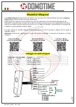
Standalone mode
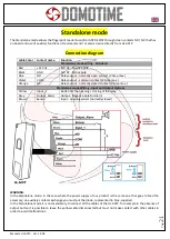
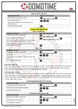
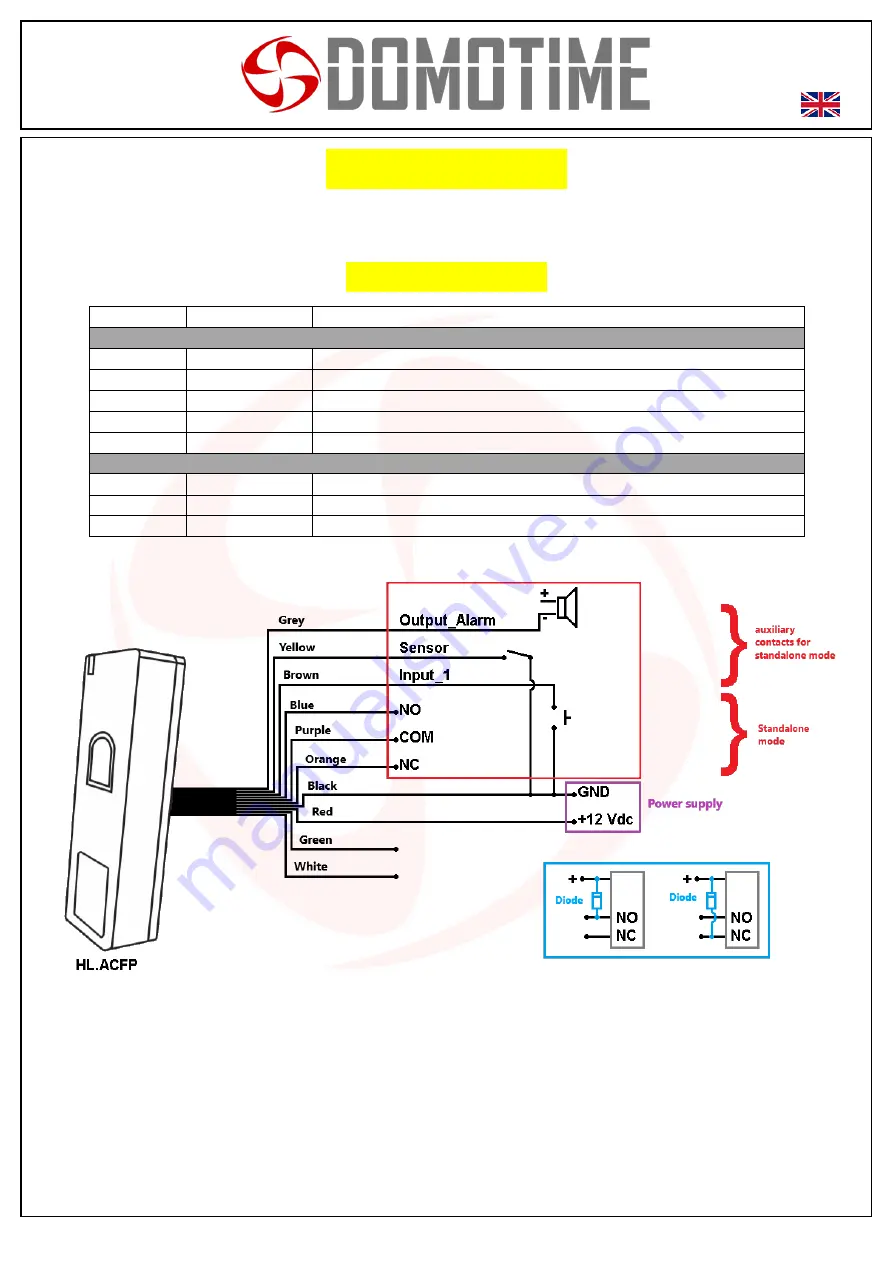
The Standalone mode allows the fingerprint reader to control ANY DEVICE through clean contacts NO / NC that has
on board and use of auxiliary functions of command and / or alarm device directly from HL.ACFP.
Connection diagram
cable Color
contact name
Function
Standalone mode wiring - Standard
Red
+12 Vdc
12V DC - Positive pole
Black
GND
12V DC - Minus pole
Blue
NO
Relay output - normally open contact (2 Amp max.)
Violet
COM
Relay output - common contact (2 Amp max.)
Orange
NC
Relay output - normally closed contact (2 Amp max.)
Standalone mode Wiring - Input and Output Options
Yellow
input_1
Button for the opening / closing of the relay
Grey
Output_Alarm
Output - Negative pole for Alarm
Brown
Sensor
Input - opening sensor (normally closed)
WARNING
:
In the Standalone mode, in the case where the power supply of our product is the same one that goes to feed the
accessory, on auxiliary contacts exchange you must put the diode, represented in blue, supplied.
In the Standalone mode it is not mandatory to connect all the cables of the HL.ACFP, for example in the absence of
output button it is possible to leave the yellow cable disconnected but must not make contact with other cables in
order to avoid malfunctions.

