background image

31

Donaldson Company, Inc.

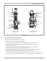
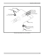
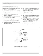
afterfilter

clamp straps

and wing

screws

power pack

mounting base
sealant

plenum

HEPA and ASHRAE Afterfilter Installation

HEPA or ASHRAE Afterfilter Installation

The afterfilter plenum is mounted on top of the unit and 
the blower is positioned inside the plenum.
1.   Apply sealant around the clean-air outlet toward the 

outside edge of the bolt hole pattern located on the 
top of the collector.

2.   Position the afterfilter plenum mounting base 

aligning the bolt patterns.

3.  Apply sealant to the plenum mounting base toward 

the outside edge of the bolt pattern. 

4.  Install the blower housing, align bolt holes, and 

fasten securely in place using hardware supplied 
with the power pack. 

5.  Assemble the remaining power pack components as 

described in Power Pack.

6.  Apply sealant to the inside perimeter of the mounting 

base. Install the plenum to the  mounting base using 
self-threading bolts with washers. 

7.  Install 1/2-in conduit using the holes on the back of 

the afterfilter plenum. Flexible 
or rigid conduit can be used.

8.  Apply sealant to the plenum’s top flange and use self-

treading bolts and washers to secure the plenum top 
to the plenum.

9.  Install the afterfilters in the afterfilter frames. Install 

HEPA filters with the gasket toward the inside of 
the frame. Install ASHRAE filters with the airflow 
direction arrow pointing outside. 

10.  Position the clamp straps and tighten the wing 

screws securely.

Summary of Contents for DFO 2-4

Page 1: ...2...

Page 2: ...bility or liability for the suitability of any fire and or explosion mitigation strategy or any items incorporated into a collector as part of an owner operators hazard mitigation strategy Improper op...

Page 3: ......

Page 4: ...rsatility of the unit standard options include top front and abrasion resistant inlets HEPA and ASHRAE afterfilter packs Checker board control panel and various dust removal options Purpose and Intend...

Page 5: ......

Page 6: ...ng system diaphragm valve compressed air supply hopper Filter Cleaning Operation dirty air inlet clean air outlet clean air outlet filter cartridges clean air plenum Normal Operation dirty air inlet o...

Page 7: ...the unit will compromise unit performance Inspect unit to ensure all hardware is properly installed and tight prior to operating collector Installation Site suitability must account for wind seismic...

Page 8: ...e capacity Allow only qualified crane operators to lift the equipment Refer to applicable OSHA regulations and local codes when using cranes forklifts and other lifting equipment Lift unit and accesso...

Page 9: ...binet 2 Apply sealant to hopper flange 3 Fasten hopper to cabinet 4 Assemble legs and cross braces 5 Lift unit and hopper into position over legs and lower slowly 6 Fasten legs to unit securely 7 Lift...

Page 10: ...hopper following these instructions 1 Stand the hopper on the discharge end 2 Apply 1 4 in diameter rope type sealant around the top flange toward the inside edge of the bolt pattern 3 Lift the colle...

Page 11: ...abinet and hopper assembly into position over the legs and lower slowly 3 Use drift pins to align the holes in the collector with the holes in the legs Attach each leg as shown using the hardware supp...

Page 12: ......

Page 13: ...o manifold solenoid electrical connection manifold solenoid enclosure diaphragm valve hopper blower fan Magnehelic gauge 120 Volt blower motor starter solid state timer safety exhaust valve Notes 1 No...

Page 14: ......

Page 15: ......

Page 16: ...upply Turn electrical power OFF at source and switch any two leads on the motor junction box Do not interchange a power lead with the ground wire Severe damage or personal injury may result 3 All acce...

Page 17: ...Downflo Oval DFO 2 4 and 3 6 14 This Page Intentionally Left Blank...

Page 18: ...lications Periodically check the compressed air components and replace compressed air filters Drain moisture following the manufacturer s instructions With the compressed air supply ON check the clean...

Page 19: ......

Page 20: ...pinching Check that access covers are seated and seal properly Gaskets must be compressed to ensure an airtight seal 3 Turn electrical power and compressed air supply ON before starting unit Dust Dis...

Page 21: ...Downflo Oval DFO 2 4 and 3 6 18 This Page Intentionally Left Blank...

Page 22: ......

Page 23: ......

Page 24: ......

Page 25: ...a forklift or pallet jack If a pallet is used the length of flexible hose may need to be shortened 1 Place 1 4 in diameter rope type sealant between the hopper flange and the drum cover mounting flang...

Page 26: ...cludes a 5 gallon pail and provides easy access for dust removal and storage 1 Apply sealant to the hopper flange or the pail cover mounting plate flange toward the inside edge of the bolt pattern 2 F...

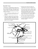
Page 27: ...in the clean air plenum 1 Choose a convenient accessible location on or near the unit for mounting that provides the best visual advantage 2 Plug the pressure ports on the back of the gauge using two...

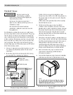
Page 28: ...in the right hand side of the mounting bracket Tighten screws 3 On the back of the gauge remove four 6 32 x 5 16 in screws and plastic enclosure Set aside Add two jumper wires supplied by customer Re...

Page 29: ...n 1 8 in NPT male adapter NPT male adapter static pressure tee dirty air plenum pressure tap location 1 8 in NPT male adapter plastic tubing two 1 8 in NPT adapters low pressure port high pressure por...

Page 30: ......

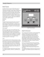
Page 31: ...Drop Off and Alarm The first two High Pressure Drop On and Low Pressure Drop Off control the filter cleaning system The third Alarm provides a relay output to activate an external alarm supplied by o...

Page 32: ...ling screws supplied 5 Loosen the wing nut on the damper and adjust from 30 to 50 closed Backward Inclined 1 Apply sealant around the inside edge of the bolt pattern on the power pack outlet 2 Fasten...

Page 33: ...omponents as described in Power Pack Assembly on Page 12 6 Attach the plenum silencer to the base using self threading bolts with washers 7 Route rigid or flexible conduit from the junction box on the...

Page 34: ...g align bolt holes and fasten securely in place using hardware supplied with the power pack 5 Assemble the remaining power pack components as described in Power Pack 6 Apply sealant to the inside peri...

Page 35: ...sion Resistant Inlet Collar 1 Remove the unit s front cover plate Remove excess sealant from opening 2 Apply 1 4 in sealant around the opening toward the inside edge of the bolt pattern 3 Align the ho...

Page 36: ...to deliver heat to the large pulse valves This kit is customer installed and detailed installation instructions are provided 1 Install the power connection kit on the heat cable following the manufac...

Page 37: ......

Page 38: ...operly Check airflow in duct Adjust damper control until proper airflow is achieved and the blower motor s amp draw is within the manufacturer s rated amps Electrical circuit overload Check that the p...

Page 39: ...d input power is present but output voltage to the solenoid is not replace the timer board See Solid State Timer Installation Solid State timer out of adjustment See Solid State Timer and Solid State...

Page 40: ...keys to not work Improper operation Press and hold one of the three setpoint keys to use arrow keys Programming keys disabled Remove the Program Disable jumper from Terminals 3 and 4 on TB2 Cleaning...

Page 41: ...Downflo Oval DFO 2 4 and 3 6 38 Service Notes Date Service Performed Notes...

Page 42: ...39 Donaldson Company Inc Service Notes Date Service Performed Notes...

Page 43: ......

Page 44: ...se The terms of this warranty may be modi ed only by a special warranty document signed by a Director General Manager or Vice President of Donaldson Failure to use genuine Donaldson replacement parts...

Reviews: