Downflo II, Models DFT 2-4 and DFT 3-6
15
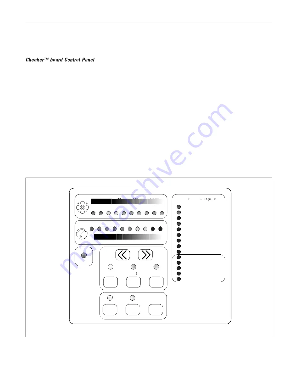
The Checker board provides cleaning control,
diagnostic review of the operational parameters,
diagnostic review of the system components, and a
record of operational data and fault conditions for
future review. The operator interface provides
control of unit functions and operational status
information.
The design allows a host computer to remotely
control the unit, accept change to operational
parameters, and check operational status.
1. Mount the control enclosure in a convenient,
accessible location that provides the best visual
advantage. Mount the enclosure to a wall or
column with little or no vibration and away
from static discharges that could damage
components.
2. Make the proper electrical and pneumatic
connections to the collector and motor starter
following the diagrams and instructions
supplied with the Checker board.
3. Verify proper blower rotation by pushing the
start-stop button ON then OFF. Rotation must
match the rotation arrow on the blower
housing as viewed from the top.
4. Calibrate the Checker board computer to the
system airflow. Establish filter cleaning settings
and service intervals.
Note:
See the Checker board Installation and
Operation Manual, IOM 7220601 for
complete installation and operating
instructions.
PANEL
STOP
CLEAN
START
CLEAN
SERVICE
INTERVAL
SET POINT AD USTMENT
CONSTANT
CLEAN
DOWN
TIME
CLEAN
SERVICE
INTERVAL
LIGHT
RESET
AIR FLOW
SET POINT INDICATOR
FILTER PRESSURE DROP
P
MAINT NANC R
IR D
PANEL
CLEANING FAILURE
FILTER RUPTURE
FILTER PLUGGED
TEMPERATURE
SERVICE INTERVAL
BLOWER OVERCURRENT
BLOWER ROTATION
COMPRESSED AIR
Checker board Control Panel


