background image

7

Donaldson Company, Inc.

Standard Equipment

Standard collectors include a fan, motor, control panel, 

10-gallon dust container, and an exhaust silencer and 

damper. Depending on the type of control selected, 

the motor may or may not be pre-wired. Otherwise, 

the collector is fully assembled and ready to connect 

to electrical supply, compressed air, and ductwork. A 

detailed drawing, shipped with each collector, provides 

weight, specifications, and collector dimensions 

including anchor bolt locations for the collector’s base 

plate.

Cleaning Controls

All collectors include standard cleaning controls that are 

manually- or timer-controlled depending on the model 

and options selected. Controls are available in a variety 

of voltages and are available in one of four basic types:
1.  Manual push-button with or without motor starter.
2.  Downtime cleaning with or without motor starter.
3.  Delta P cleaning with or without motor starter.
4.  Manual push-button, Delta P, or downtime cleaning 

without motor starter in a remote-mount option.

Model DFO 1-1 standard controls include a manual  

motor starter that is prewired to the motor and a push-

button valve for pulse cleaning control. Options include 

downtime cleaning with or without motor starter and 

remote-mount, downtime cleaning without motor starter. 
Models DFO 2-2 and DFO 3-3 standard controls include 

downtime cleaning without a motor starter. Available 

options include downtime cleaning with a motor starter, 

remote-mount downtime cleaning without motor starter, 

Delta P cleaning with or without motor starter, and 

remote-mount Delta P cleaning without motor starter.
All control panels, except remote-mount, are located 

inside the collector.

Manual Motor Starter Option

The manual motor starter is the standard option for 

Model DFO 1-1 and is not available for other models. It 

is prewired to the motor and filter cleaning is completed 

using a separate, manual push-button valve located next 

to the motor starter.

Downtime Cleaning Option

Primarily used for intermittent duty, light dust-load 

applications, the downtime cleaning option provides 

automatic, downtime filter cleaning when the collector 

is turned OFF. Downtime cleaning WILL occur every time 

the collector is shut down. The valves start to pulse one 

minute after the collector is shut down and continue 

pulsing every 10-seconds for 3 minutes to reduce the 

differential pressure. 
Downtime cleaning without motor starter is standard for 

Models DFO 2-2 and DFO 3-3. The option is specified at 

the time of order and available with and without a motor 

starter. 

Delta P Cleaning Option

Primarily used for continuous duty or heavy dust-load 

applications, the Delta P option provides automatic, on-

line filter cleaning. The high- and low-pressure setpoints 

initiate the pulse cleaning cycle. The pulse-cleaning 

cycle begins when the filter pressure reaches the high-

pressure setpoint. The valves continue to pulse every 10 

seconds until the low-pressure setpoint is reached. 
The Delta P option is available for models DFO 2-2 and 

DFO 3-3 only, with or without a motor starter.

Remote-Mount Cleaning Option

Primarily used in applications that require the cleaning 

controls to be located away from a hazardous 

environment, remote-mount controls are available with 

downtime cleaning and Delta P cleaning options. Remote 

downtime cleaning is available for all three models 

while the remote Delta P is available for models DFO 2-2 

and DFO 3-3 only. This option is specified at the time of 

order and the collector is equipped with a 115-Volt AC 

NEMA 12 solenoid valve enclosure. Explosion-protected 

collectors include a NEMA 9 dust explosion-proof 

solenoid enclosure. Contact Donaldson for information 

about a NEMA 7 gas explosion-proof solenoid enclosure.
Motor starters for remote-mount cleaning options are 

customer-supplied.

Summary of Contents for Downflo Oval DFO 1-1

Page 1: ...ngs in this manual DO NOT operate or perform maintenance on this collector until you have read and understood the instruction and warnings contained within this manual Downflo Oval DFO 1 1 2 2 and 3 3...

Page 2: ...ipment This manual has been supplied to assist with the installation operation and maintenance for the collector purchased Please read the manual before installing operating or performing maintenance...

Page 3: ...Wiring 9 Control Panel and Motor Wiring 10 Control Panels and Solenoid Specifications 13 10 Gallon Pail Pack 14 25 Gallon Dust Bin 14 Exhaust Damper 14 Preliminary Start Up Check 15 Maintenance Infor...

Page 4: ...r control Donaldson does not provide engineering consulting services related to process or dust hazard analyses or code and standard compliance Complying with applicable codes and standards and managi...

Page 5: ...ifications Hygroscopic dust such as fertilizer salt and sugar should be handled under a controlled low humidity environment Flammable or explosive dust may require customized collector design options...

Page 6: ...es through the clean air outlet Filter cleaning is completed using pulse jet technology An air diaphragm valve aligned to each filter provides the pulse cleaning Either a manual push button valve or e...

Page 7: ...collector will compromise collector performance Inspect collector to ensure all hardware is properly installed and tight prior to operating collector Installation Use proper equipment and adopt all s...

Page 8: ...or and accessories separately and assemble after collector is in place Hoisting Information Failure to lift the collector correctly can result in severe personal injury and or property damage Use appr...

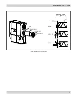
Page 9: ...Downflo Oval DFO 1 1 to 3 3 6 Typical Installation Typical Installation...

Page 10: ...models It is prewired to the motor and filter cleaning is completed using a separate manual push button valve located next to the motor starter Downtime Cleaning Option Primarily used for intermittent...

Page 11: ...plate and shims grout Embedment depth suitable for the physical properties of the foundation Collector Anchoring Anchors must comply with local code requirements and must be capable of supporting dead...

Page 12: ...erforming service or maintenance work Do not install in classified hazardous atmospheres without an enclosure rated for the application Electrical Wiring All electrical wiring and connections includin...

Page 13: ...valve regulator compressed air supply bleed type air filter automatic condensate valve power supply disconnect switch motor starter customer supplied Turn power off and lock out electrical power sour...

Page 14: ...cable Downtime Cleaning without Motor Starter G ground lug TR1 L N N N FU1 PS1 N L G 120 Volt AC Delta P Cleaning with Motor Starter L3 L2 L1 1L3 1L2 1L1 ground lug PE PE 1L1 1L2 3 Phase OL M1 fused...

Page 15: ...elay outputs located inside the control panel Delta P Cleaning Wire 120 Volt AC power directly to the control panel two point terminal block located on the 3 pin timer subpanel Solenoid Connection Wir...

Page 16: ...y set at 200 milliseconds Pulse OFF Time Factory set at 10 seconds The pulse OFF time can only be adjusted by modifying the parameters contained in the microprocessor software Contact your representat...

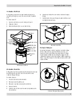
Page 17: ...bin and clamp down with draw latches Exhaust Damper Adjustment 10 Gallon Pail Pack hopper flexible hose hose clamp 10 gallon pail pail cover hex bolt flat washer hex nut sealant cover clamp adapter c...

Page 18: ...ads on the motor junction box Do not look into fan outlet to determine rotation View the fan rotation through the back of the motor Check that the exhaust plenum is free of tools or debris before chec...

Page 19: ...Maintenance Information Operational Checklist 1 Monitor the physical condition of the collector and repair or replace any damaged components Routine inspections will minimize downtime and maintain op...

Page 20: ...yoke Note Insert the filter gasket end first 2 Wipe cover gaskets clean and replace covers by attaching cover to yoke hook and firmly latching cover handle Replace access covers carefully by securing...

Page 21: ...Downflo Oval DFO 1 1 to 3 3 18 Filter Access Cover Removal Side View access cover yoke latched unlatched removal access cover cover handle filter cartridge yoke Filter Removal and Installation...

Page 22: ...ing onto shaft If it does not go on easily check shaft bushing and key sizes once again Tighten capscrews gradually and evenly with wrench similar to mounting an automobile wheel Rotate a quarter turn...

Page 23: ...gallon dust container is secured to the adapter collar with a band clamp similar to the standard 10 gallon dust container 1 Apply sealant to the adapter collar mounting flange toward the inside edge...

Page 24: ...o seal the dust container To install on an existing collector 1 Remove the cover and clamp from the dust container 2 Remove the dust container and set aside 3 Remove the flexible duct and adapter coll...

Page 25: ...reating a pressure drop The Delta P Controller measures the pressure drop and provides a visual display in inches water gauge or metric SI units of daPa Filter Cleaning When the pressure drop across t...

Page 26: ...1 Lift collector approximately 24 in with a crane or forklift 2 Position the swivel caster assembly under the front filter access end of the collector Align bolt holes and secure using the 3 8 16 x 5...

Page 27: ...in the roof panel using a 0 266 in diameter drill bit 5 Apply 1 4 in diameter rope type sealant toward the inside of bolt pattern 6 Position the HEPA mounting frame on the top panel aligning the bolt...

Page 28: ...he mounting adapter on the roof panel aligning the bolt holes from the bolts removed in Step 1 with the bolt pattern on the mounting adapter Note The bolt pattern of the mounting adapter is not symmet...

Page 29: ...4 in flat washer 1 4 in lock washer 1 4 20 hex nut mounting adapter inlet flange Extraction Arm Ex Arm Installation Extraction Arm Installation Lift the Ex Arm into position over the mounting adapter...

Page 30: ...ng of an explosion must be safely directed outdoors away from areas occupied by personnel to reduce risk of personal injury and or property damage The risk of personal injury and or property damage ca...

Page 31: ...perly Check airflow in duct Adjust damper control until proper airflow is achieved and the blower motor s amp draw is within the manufacturer s rated amps Electrical circuit overload Check that the po...

Page 32: ...wiring diagram inside the control panel Replace if necessary Display on Delta P Controller does not read zero when at rest Out of calibration Recalibrate as described in Delta P Maintenance Manual Wit...

Page 33: ...wiring Check wiring between the Delta P Control and the timer board and between the timer board and solenoid valve coils Defective solenoids Check all solenoid coils for proper operation Timer board n...

Page 34: ...__________________________________________________________ Dust Properties Kst_______________Pmax______________MIE____________MEC_________________ Accessories__________________________________________...

Page 35: ...foregoing warranty on services Products manufactured by a third party Third Party Product may constitute contain be contained in incorporated into attached to or packaged together with the goods Buye...

Page 36: ...Many factors beyond the control of Donaldson can affect the use and performance of Donaldson products in a particular application including the conditions under which the product is used Since these...

Reviews: