9
Donaldson Company, Inc.
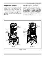
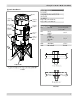
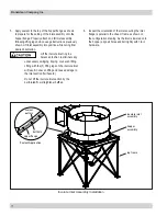
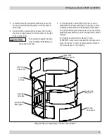
I-beam frame
leg
back-to-back
angle iron
cross-bracing
Anchors must comply with local
code requirements and must be
capable of supporting dead, live,
wind, seismic, and other applicable loads.
Anchor sizes shown are provisional, as final
anchor sizing will depend on jobsite load
conditions, collector location, foundation/framing
design variables and local codes.
Consult a qualified engineer for final selection of
suitable anchors.
Leg Installation
Temporary support is required until
all legs and cross-bracing are in
place.
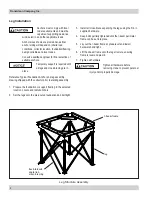
2. Set the legs onto the pre-poured foundation and bolt tight.
Leg Structure Assembly
3. Install all cross-braces spanning the legs using the 3/4-in
supplied hardware.
4. Keep bolts partially tightened until the I-beam perimeter
frame can be set into place.
5. Lay out the I-beam frame at grade level and install
hardware hand tight.
6. Lift the I-beam frame onto the leg structure, ensuring
frame is level and plumb.
7. Tighten all hardware.
Tighten all hardware before
removing crane to prevent personal
injury and/or property damage.
Reference Typical Foundation Anchor and leg assembly
drawing shipped with the collector prior to starting assembly.
1. Prepare the foundation or support framing in the selected
location. Locate and install anchors.


