Installation, Operation and Maintenance Manual
Unimaster Dust Collectors – Series UMA 40-750
29
MAINTENANCE
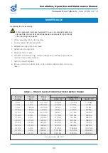
Filter resistance can be checked by connecting a U-tube manometer or differential-
type pressure gauge to tapping points (if fitted) on the unit casing. This will give
a continuous indication of the state of the filter. Normally a resistance of 75 to
125 mm WG may be expected for all collectors except the UMA 750, depending
on the air volume and the characteristics of dust being handled, increasing slightly
until the collector is cleaned. For UMA 750 collectors, a resistance of 125 to
175 mm WG may be expected.
The secondary or absolute filter monitor, if fitted, will provide a constant indication
of the state of the secondary or absolute filter element.
It is recommended to periodically inspect the general casing integrity.
It is recommended that door fastener threads are lubricated at regular intervals
(applicable to collectors fitted with explosion relief).
Ignition minimising fans are fitted with a lining inside the casing. As
this may only offer protection for a limited period, any upset condition
leading to rubbing, the fan must be switched off immediately and the
condition corrected.
Servicing schedule
A record of all pressure checks should be kept in a log book to aid the speedy
diagnosis of faulty operation.
Weekly
Measure the pressure drop across the filter assembly (use tapping points, if fitted).
Record the figure in the log book. If the pressure drop increases significantly over
two or three successive checks, e.g. 50% (a variation of up to 10% is permissible)
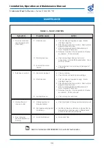
check the filter as described in Table 3.
If the collector is fitted with a secondary or absolute filter, then the pressure drop
across this filter should also be checked if a filter monitor is not fitted. The filter
should be changed when the pressure drop reaches 100 mm W.G.
Unimaster collectors fitted with an explosion relief assembly should be
inspected weekly to ensure the burst ing panels are intact and clear of
obstruction. During winter, particular care must be taken to prevent
build-up of snow or ice on explosion panels.
Six-monthly
The fan impellor has been dynamically balanced and the fan assembly vibration
level should be in line with category BV-3, ISO 14694. An assessment of vibration
should be made every six months, or after a significant emission, or after any
misuse and a record kept of measured values. Excessive vibration levels should
be investigated and corrected immediately.
Vibration monitoring is mandatory on category 2G, 3G and 2D fan
assemblies.


