background image

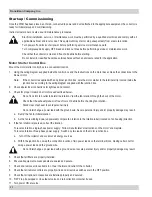
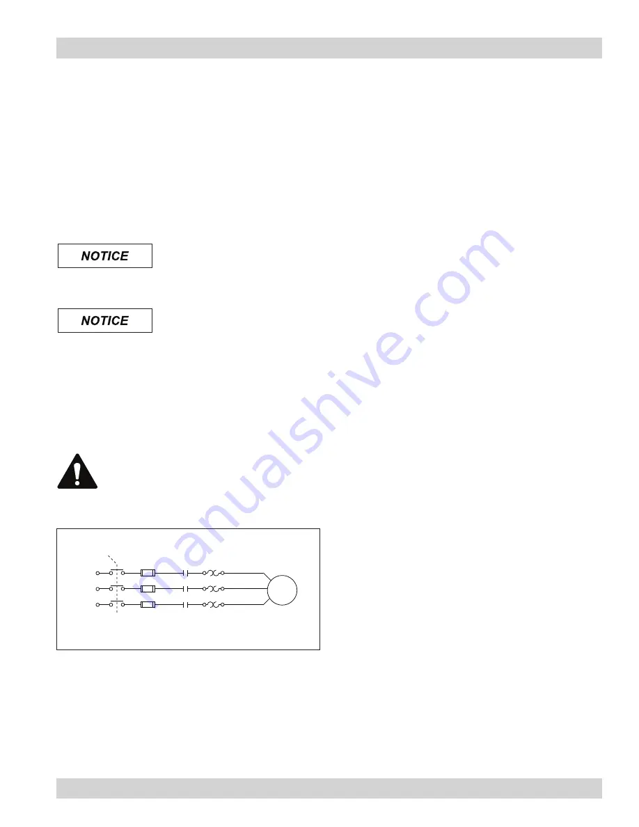
WSO collectors must be equipped with a customer-supplied safety disconnect with short circuit protection, contactors, and 

overload protection. Complete the wiring as shown in Motor Starter Wiring.

Pre-Wired Collectors

Pre-wired collectors include contactors and overload protection and requires a customer supplied safety disconnect switch. 

Complete the wiring as shown in Motor Starter Wiring.

Unwired Collectors

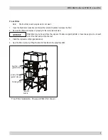
1.  Remove the exhaust pack. Remove all bolts and lift starting at one corner.

The gasket material is fragile and must be handled with care. If the gasket is disrupted, reposition evenly 

around the inner and outer flanges when replacing the exhaust panel.

2.  Make the wiring connections to the fan motor according to the wiring diagram located inside the control box and the 

instructions on the motor decal.

All electrical components must be sized for the supply voltage and motor horsepower. See Motor Starter 

Wiring.

3.  Reinstall exhaust pack.
4.  Turn the fan-motor ON then OFF and check for proper rotation by viewing through the opening on top of the collector.
 

To reverse rotation, single-phase power supply: 

Follow manufacturer’s instructions on the motor’s nameplate.


To reverse rotation, three-phase power supply: 

Switch any two leads on the motor junction box.

Check that the exhaust plenum is free of tools or debris before checking fan rotation.

Stand clear of exhaust to avoid personal injury.
Do not interchange a power lead with the ground wire. Severe personal injury and/or property damage may result.

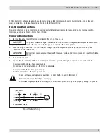
1FU

2FU

3FU

1M

1OL

1T2
1T3

fan

motor

Disconnect

1T1

1L1

1L2

1L3

208/230/460/575/60/3

Motor Starter Wiring

WSO Mist Collector, WSO 25-4 and 25-6

 22

Summary of Contents for WSO 25-4

Page 1: ...Master Language This manual contains specific precautions related to worker safety The hazard alert image denotes safety related instructions and warnings in this manual DO NOT install operate or perform maintenance on this collector until you have read and understood the instructions precautions and warnings contained within this manual WSO 25 4 WSO 25 6 ...

Page 2: ... the installation operation and maintenance for the collector purchased Please read the manual before installing operating or performing maintenance on the collector as it contains specific precautions for worker safety It is the owner s responsibility to ensure that this manual is available for use by installers operators and maintenance personnel that will be working with this collector This man...

Page 3: ...oubleshooting 11 Appendix A Installation 13 Installation 14 Location and Site Selection 14 Delivery and Inspection 14 Unloading and Positioning 14 Support Installation 15 Electrical Wiring 15 P Trap Installation 17 Inlet Plenum Installation 17 Options and Accessories 18 Cleaning Controls and Sensors 18 Magnehelic Installation 18 Damper and Silencer TBI WSO Unpowered 25 4 and 25 6 20 Top Mount 20 S...

Page 4: ...gement activities and should comply with applicable codes and standards related to combustible mist Electrical installation must be performed by a qualified electrician This equipment is not designed to support site ducts piping or electrical services All ducts piping or electrical services must be adequately supported to prevent injury and or property damage Site selection must account for wind s...

Page 5: ...y liability for the fitness of a mitigation strategy or product for a particular installation or application The process owner s final selection of dust collectors and risk mitigation strategies should be based on the outcome of a Dust Hazard Process Hazard Analysis performed by the process owner Although early engagement of a dust collector supplier provides helpful insights on the availability a...

Page 6: ...rking fluids suspended in the air Metalworking fluids include straight oils water soluble coolants semi synthetic and synthetic coolants These fluids perform a variety of functions such as lubricating or cooling the part or the tool flushing chips away from the part and suppressing dust and smoke Mist is created two ways mechanical action or thermal effects Mechanical action involves coolant used ...

Page 7: ...ollect and coalesce large coolant droplets which drain into the hopper Primary Filter After passing through first stage filter prefiltered air then passed through a primary filter where fine coolant droplets and mist coalesces and again drain into the hopper Final Filter Optional Filter air can then be passed through a final filter to separate fine dust particulates which may have passed through t...

Page 8: ...the collector The droplets will drain on both the inside and outside of the cartridge Liquid that collects on the inside of the cartridge drains through the bottom portion of the porous media and into the hopper Clean mist free air exits the cartridge and discharges through the top of the collector optional afterfilter primary filter cartridge first stage filter P trap drain clean air outlet fan c...

Page 9: ...1 Monitor the physical condition of the collector and repair or replace any damaged components Routine inspections will minimize downtime and maintain optimum system performance This is particularly important on continuous duty applications 2 Monitor pressure drop across filters Abnormal changes in pressure drop may indicate a change in operating conditions and possibly a fault to be corrected 3 M...

Page 10: ...r the materials collected Note A large plastic garbage bag placed over the top of the used filter allows cleaner filter change out The filter can be tipped forward and out of the collector while the bag is pulled up over the bottom of the cartridge 2 Place new filter on the filter retention platform gasket side up Slide filter back as far as it will go Note The primary filter must be replaced Do n...

Page 11: ...he materials collected Dirty filters may be heavier than they appear Provide a support platform or have two people one on each side of the filter and pull the filter out 3 Install the replacement filter gasket side up 4 Seal the filter in place by lifting the retention handles to the upright position Final Filter Installation Powered WSO 25 6 shown primary filter gasket side up final filter gasket...

Page 12: ...w fluid and particulate to drain 3 With the clean out valve open slowly open the P Trap valve This allows fluid still trapped in the hopper to drain A substantial amount of fluid may be trapped in the hopper and could exceed the container capacity Open the P Trap valve slowly 4 Close the P Trap valve 5 Unscrew the screen cap and pull the screen out 6 Clean the screen and the inside of the Y strain...

Page 13: ...he fan Only qualified crane or forklift operators should be allowed to lift equipment To avoid personal injury and or damage to equipment ensure fan blowers are properly attached to equipment The use of a damper or variable frequency drive VFD is required to control airflow through the collector Lack of a control damper or VFD will shorten filter life The collector can accept direct mounted fan bl...

Page 14: ...oors are open or not closed tight Close and tighten access doors See Filter Installation Electrical circuit overload Check that the power supply circuit has sufficient power to run all equipment Clean air outlet discharging oil mist Filters not installed correctly See Filter Installation Filter damage dents in the end caps gasket damage or holes in media Replace filters as necessary Use only genui...

Page 15: ...discharge Plugged hopper screen Remove and clean hopper screen Plugged P Trap Clean P Trap See P Trap Service Liquid leaking from collector door Plugged P Trap Clean P Trap See P Trap Service Plugged or full drain collection container Remove and clean or empty the drain collection container ...

Page 16: ...Donaldson Company Inc 13 Appendix A Installation ...

Page 17: ...y connections Site selection must account for wind seismic zone and other load conditions Collector intended for indoor installation and can be located on a foundation structural framing suspended or hung from overhead supports The equipment must be anchored once in final position Consult a qualified engineer for final selection of foundation or support framing Note Ensure the inlet has at least f...

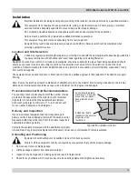
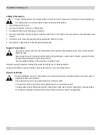
Page 18: ...obsite load conditions equipment location foundation framing design variables and local codes Consult a qualified engineer for final selection of suitable anchors Reference typical leg assembly drawing shipped with the collector prior to starting assembly Prepare the foundation or support framing in the selected location Locate and install anchors Lifting Information Failure to lift the equipment ...

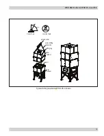
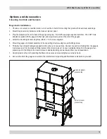
Page 19: ...st Collector WSO 25 4 and 25 6 16 30 o Max 60o Min Correct Axis Incorrect Axis Typical Lifting Guidance WSO 25 4 shown spreader bar correct lifting orientation lifting lug filter cabinet sealant inlet plenum ...

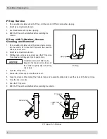
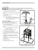
Page 20: ...entation 8 Set cabinet on top of the inlet plenum flange and attach with the supplied fasteners 9 Remove crane or forklift 10 Re install the first stage and primary filters Inlet Plenum Installation WSO 25 4 shown leg foundation anchor bolt inlet plenum P Trap Installation Ensure collected material properly flows through the P Trap The P Trap dimensions should accommodate a column of coolant great...

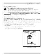
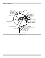
Page 21: ... 6 32 x 1 4 in screws supplied 5 Mount the gauge and bracket assembly to the supporting structure using two self drilling screws 6 Thirty five feet of plastic tubing is supplied and must be cut in two sections Connect one section of tubing from the gauge s high pressure port to the pressure fitting located in the dirty air plenum Connect remaining tubing from the gauge s low pressure port to the f...

Page 22: ...n mounting screws mounting bracket static pressure tee 1 8 in NPT x 90 elbow 1 8 in NPT adapter 1 8 in NPT adapter 3 8 in flat washer dirty air plenum pressure tap location 1 8 in NPT adapter 1 8 in NPT x 90 male elbow two self drilling screws two 1 8 in NPT pipe plugs plastic tubing two 1 8 in NPT adapters low pressure port high pressure port Magnehelic gauge 1 8 in NPT x 90 male elbow ...

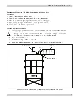
Page 23: ...ng support brackets to extend a minimum of 30 in from the collector and mark the drill locations Thoroughly clean any collected coolants or material from the collector prior to drilling to reduce the risk of combustion Failure to comply may result in personal injury and or property damage b Drill pilot holes with a 0 339 in bit c Secure brackets using 3 8 in thread forming bolts d If a gap exists ...

Page 24: ...cause the leg structure to collapse Consult with local authorities when installing fire control systems on dust collection equipment Sprinkler couplings are provided for the convenience of fire control system installers The fire control system installer shall make their own decisions on the appropriate location of fire control system components Donaldson Company Inc 21 ...

Page 25: ...iring diagram located inside the control box and the instructions on the motor decal All electrical components must be sized for the supply voltage and motor horsepower See Motor Starter Wiring 3 Reinstall exhaust pack 4 Turn the fan motor ON then OFF and check for proper rotation by viewing through the opening on top of the collector To reverse rotation single phase power supply Follow manufactur...

Page 26: ...n box swap the connection location of two power leads on the terminal block making certain not tot swap a power lead and the ground wire Do not interchange a power lead with a ground wire or severe personal injury and or property damage may result 5 Check that all filters are properly installed 6 Ensure all equipment access panels are sealed and secure 7 Check and remove all loose items in or near...

Page 27: ...Out all energy sources 2 Remove all filters from the collector and dispose of in a suitable fashion for the mist in the collector See Filter Replacement for instructions Close and secure front access doors after filters are removed 3 Disconnect electrical power from the collector and remove any associated conduit or hardware from the exterior of the collector 4 Seal the inlet and discharge opening...

Page 28: ...__________________________________________________________________________________ Dust Properties Kst________________Pmax_______________ MIE_____________ MEC___________________ Accessories____________________________________________________________________________________ Other_________________________________________________________________________________________ _______________________________...

Page 29: ...WSO Mist Collector WSO 25 4 and 25 6 26 Service Notes Date Service Performed Notes ...

Page 30: ...27 Donaldson Company Inc Service Notes Date Service Performed Notes ...

Page 31: ...ducts manufactured by a third party Third Party Product may constitute contain be contained in incorporated into attached to or packaged together with the goods Buyer agrees that a Third Party Products are excluded from Seller s warranty in this Section 7 and carry only the warranty extended by the original manufacturer and b Seller s liability in all cases is limited to goods of Seller s design a...

Page 32: ...y within the user s knowledge and control it is essential the user evaluate the products to determine whether the product is fit for the particular purpose and suitable for the user s application All products product specifications availability and data are subject to change without notice and may vary by region or country Significantly improve the performance of your collector with genuine Donald...

Reviews: