INSTALLATION, USE AND MAINTENANCE
GBA-GBP-CBE-MBE SERIES
35
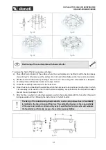
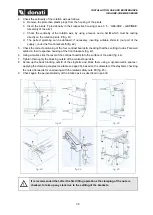
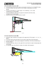
4. Check the verticality of the rotation axis as follows:
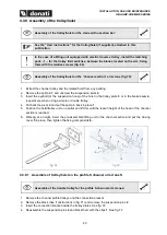
a. Remove the protective plastic plugs from the housing of the pivots
b. Insert the pivots
7
provisionally in their respective housing (see 4.3.5 -
”)
c. Check the verticality of the rotation axis, by using a level
L
and a bar
B
which must be resting
directly on the rotation pivots
3
d. The perfect plumbing can be obtained, if necessary, inserting suitable shims
4
(not part of the
supply), under the front brackets
5
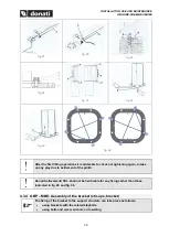
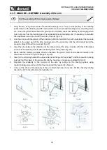
5. Check the correct positioning of the four contrast boards
6,
checking that the centring crowns
7
are well
settled in their respective housing of the front brackets (fig. 43).
6. Using a mallet, stick the level of the contrast boards
6
to the surface of the pillar (fig. 44).
7. Tighten thoroughly the blocking nuts
8
of the contrast boards
6.
8. Screw up the back blocking nuts
9
of the staybolts and block them using a dynamometric spanner,
applying the clamping couples (see table on page 26), based on the diameter of the staybolts, checking
the nuts afterwards for unscrewing with the related safety nuts
10
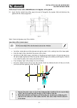
9. Check again the perpendicularity of the rotation axis as described in point
4
fig. 41
fig. 42
fig. 43
fig. 44
fig. 45
It is recommended that, after the first lifting operations the clamping of the nuts is
checked, to take up any slack due to the settling of the brackets.


