INSTALLATION, USE AND MAINTENANCE
GBA-GBP-CBE-MBE SERIES
38
4.3.6 S profiles channel arm
4.3.7 Mounting of the trolley block inside the S profile channel arm
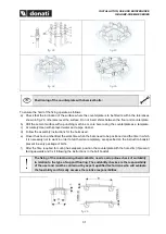
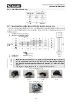
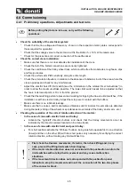
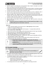
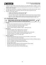
To correctly assemble the trolley block, first of all a suitable work environment is needed to drill the channel
profile. The correct drilling scheme is shown in the figure below (dis.1) and the dimensions can be found in
the following table
•
Arm S1: D2=32mm e
Φ=9.5mm
•
Arm S2: D2=50mm e
Φ=9.5mm
Arm length (m)
D1
2
3
4
5
6
7
Capacity
(kg)
63
430
490
590
650
125
360
430
430
490
590
650
250
360
430
500
530
590
650
500
400
460
460
530
620
690
800
690
1000
400
460
490
560
620
1. Trolley block
2. Fixing bolts
•
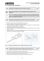
Before inserting the trolley block S1, tighten the provided blots (fig. 54) to realize
the seat for the head of the screws (fig. 55 e fig. 56) This passage will simplify the
next fixing operation becaus
e when the bolts are removed, the screws don’t move.
•
In trolley blocl S2 (fig. 58) the bolts are welded with the main body.
Internal trolley bumper S1
fig. 54
fig. 55
fig. 56
fig. 57
Internal trolley bumper S2
fig. 58
S1
S2
Capacity (kg)
Arm Length (m)
63
4-5
6-7
125
2-3-4-5
6-7
250
2-3-4
5-6-7
500
/
2-3-4-5-6-7
800
/
7
1000
/
2-3-4-5-6


