INSTALLATION, USE AND MAINTENANCE
GBA-GBP-CBE-MBE SERIES
36
4.3.5 GBA/CBE
– GBP/MBE: Assembly of the arm
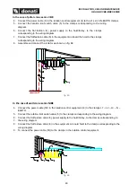
For the assembly of the arm proceed as follows:
1.
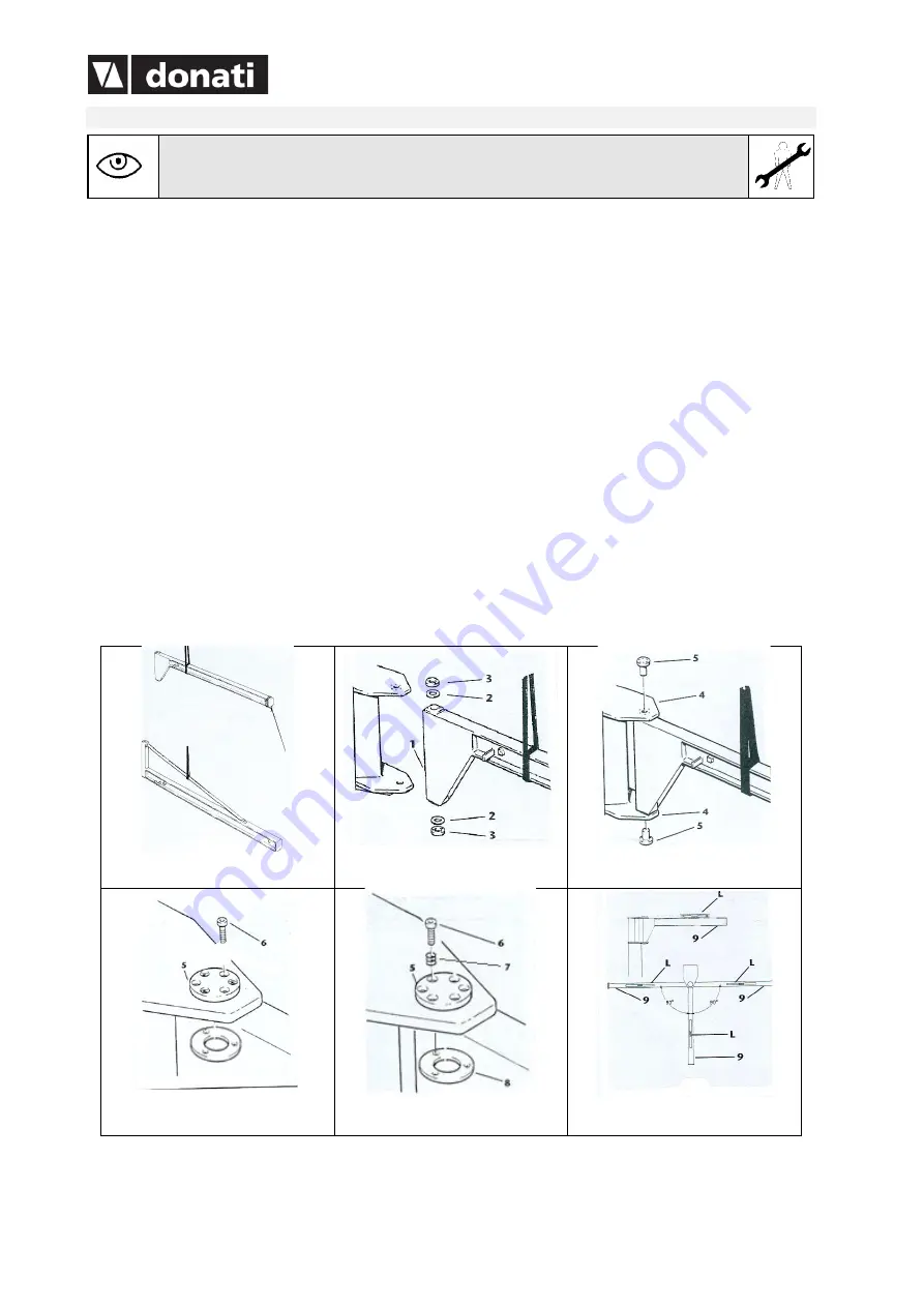
Sling the arm, using strips made of textile fibre arranged in a “loop”, corresponding to the handling
points shown on the labelling and lift it with suitable means (overhead travelling crane, travelling crane,
etc.). Keep the girder horizontal to the ground and constantly check the stability of the slinging which
must not move from the handling point. Avoid oscillations and swinging and, if necessary, to maintain
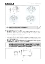
the equilibrium use a rope tied to the ends of the arm (fig. 46).
2.
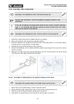
Line the arm up with the plates (of the bracket or pillar) and position the clutch plate
2
and the pressure
plate
3
in the upper part of the tube, making sure at the same time that the clutch plate
2
and the
pressure plate
3
fit into the lower part (fig. 47).
3.
Insert the tube between the plates
4
until the rotation axis of the tube coincides with that of the plates
and insert the rotation pivots
5,
after lubricating them with grease (fig. 48).
4.
Block, with the clamping couples shown in the table, the pivots
5
with their related screws
6
in the
three holes at 120 on the pivots’ flange
5
5.
Insert in the remaining holes of the upper side pivots’ flange
5
, the springs
7
and the screws
6
checking
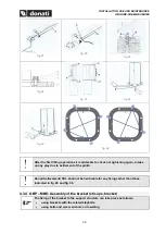
carefully that the shank of the screws fits into the housing on the pressure plates
8
6.
Regulate the slidability of the rotation of the arm, by acting on the braking system using
register/adjuster screws
6,
until the traverse sensitivity required is obtained.
7.
Carry out the check of the planarity of the arm
9
with the help of a level
L.
Do this check by rotating
the arm by 90° to the left and to the right (fig. 51).
fig. 46
fig. 47
fig. 48
fig. 49
fig. 50
fig. 51

