INSTALLATION, USE AND MAINTENANCE
GBA-GBP-CBE-MBE SERIES
39
4.3.8 Assembly of the electric system with the connector block
For the assembly of the electric system proceed as follows:
1. Extract the cable, the sleds or slides and the other electrical components from any packing
2. Insert the power cable 1 in the cable-carrying sleds 2, in the case of the channel - bar (fig. 59), or in
the slides 3, in the case of the “girder” arm (fig. 60), so as to form a series of festoons of equal width.
Tighten the cable with the related screws or seatings.
3. Insert the sleds, or slides, in the relative sliding housings (channel-girder or double-
T“girder”) - (fig.
In the case of the GBA pillar-mounted crane:
4. Connect the electric cable 1 and the cable of line (inserted previously in the pillar
– CBE: Assembly of the pillar (foundation plate, counterplate, pillar)” - Pos. 2) - to the terminals 4
contained in the connector block (fig. 62).
In the case of the GBP wall-mounted crane:
4. Connect the electric cable 1 to the terminals 4 contained in the connector block, to be applied to the
pillar or load-bearing wall and to which the cable of line coming from the power supply will be connected
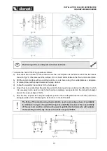
fig. 59
fig. 60
fig. 61
fig. 62
fig. 63
fig. 64
The user or installer assigned by the user must:
•
install, in the immediate vicinity of the crane, a line switch, protected against short
circuits, showing its function with the appropriate label.
•
Have earthing connected, to the structure of the crane, corresponding to the
handling points for this Purpose (fig. 64).


