INSTALLATION, USE AND MAINTENANCE
GBA-GBP-CBE-MBE SERIES
43
4.3.9 Assembly of the trolley/hoist
Assembly of the trolley/hoist on the crane with a section bar:
See the “User instructions” for the trolley/hoist (if supplied), attached to this
publication
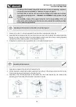
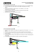
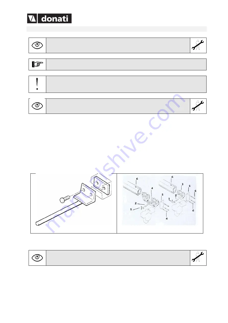
In the case of a lifting unit equipped with electric traverse trolley, install the matching
parts - 1 -, for the trolley limit switches, between the blocks located on the arm, fixing
them with the relative screws (fig. 69).
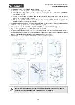
Assembly of the trolley/hoist on the “channel section” arm crane (fig. 70):
1. Extract the channel trolley and the related hoist from any packing
2. Remove the split pin
1
and unscrew the suspension pivot
2
3. Insert the eyebolt (or the suspension hook) of the hoist in the trolley plate
3
or in the brake beam
4
,
respectively, when using a simple or double trolley.
4. Put back the pivot
2
and put the split pin back in place
1
5. Position the hoist/trolley unit on a pallet and lift this until the lead-in height of the head of the channel
section is reached.
6. Working at a height, insert the pre-assembled lifting unit in the channel section and put the closing
cover
5
in place, then tighten the fixing components
6.
fig. 69
fig. 70
4.3.9.1 Assemble of trolley/hoist on the profile S channel arm crane S
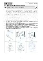
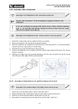
Assemble of the double trolley for the profile S channel arm cranes:
1. Remove the channel profile trolleys and the connection bracket
2. Remove the block clips
1
(instructions in fig. 71)
and remove the suspension pins
2
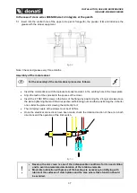
3. Insert the connection bracket inside the trolley plates. See fig. 72
4. Reassemble the suspension pins
2
and block them with the clips
1
. See fig. 72

