MAN05MGO5
INSTRUCTIONS JIB CRANE SERIES GBA - GBP
17
3.5.1 Control devices
The manually rotated
jib cranes,
in the GBA column-mounted version and the GBP wall-mounted version can be
controlled in the following ways:
1. If fitted with an
electric hoist and push-trolley
the movements are activated:
•bya
push-button panel
with ascent and descent buttons to control the
lifting
movement.
•by
pushing the load
for the control of the
trolley.
2. If fitted with an
electric hoist and electric trolley
the movements are activated:
•bya
push-button panel
with ascent and descent buttons to control the
lifting
movement.
•bya
push-button panel
with right and left buttons to control the
translation
of trolley.
3. If fitted with a
hoist and manual trolley
the movements are activated:
•by
mechanical working
of the chain of the hoist for the
lifting
movement.
•witha
push of the load
for the control of the
trolley.
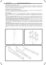
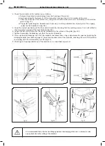
4. In all cases the
rotation movement of the jib crane arm,
both in a clockwise and anti-clockwise direction, is
activated manually, with a
pushing flexing of the load
(fig. 8).
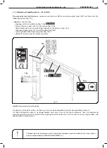
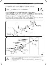
3.5.2 Safety and emergency devices
The manually rotated
jib cranes
in the GBA column-mounted version and the GBP wall-mounted version, are fitted
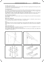
with the following safety and emergency devices (fig. 9):
1.
Rotating brake,
by friction, which allows the regulation of the arm’s rotating force and ensures the stability of
positioning.
2.
Trolley-end limit switches,
mechanical catches which limit the maximum run of the trolley along the arm’s
girder.
3.
Mechanical limit switch actuators
(in the case of the crane with electric trolley), limit switch striker plates of
the trolley’s electrical microswitches.
4.
,IMITSWITCHESFORTHEARMSENDSSUPPLIEDONREQUEST
mechanical catches which limit the maximum rotation
of the arm.
5.
Anti-collision device, available on request,
to avoid the telescoping of two or more arms which, operating in
the same area, can interfere with each other; or to avoid the collision of the arm with surrounding structures.
3.5
Safety measures and instructions
fig.8
fig.9
1
3
2
KMAN05MG05

