24
INSTRUCTIONS JIB CRANE SERIES GBA - GBP
MAN05MGO5
4.3.3 Assembly of the column – For GBA column-mounted cranes
Positioning of the foundation frame in the plinth:
•Thefixingofthecolumntothegroundcanbedoneinthefollowingways:
•usingafoundationframewithlogboltssunkintoaplinthmadeofreinforcedconcrete
•usingthebigplateandscrewanchorsordowelling.
•Thefixingofthecolumnusingboltsandscrewanchorsordowellingrequiresascrupulouscheckof
suitabilityinrelationtothetypeofsupportflooring.
•Thetechnicaldata,sothattheusercanchoosetherightsizeforthethefoundationplinth,areshown
in the table in paragraph 2.2.7
(“Fixing systems”p.12)
.The plinth size must be in relation to the real
consistencyofthegroundandthespecificmaximumpressurethatitcanbear.
•Thesuitabilitychecksofthefoundationaretheresponsibilityoftheuserandmustbecarriedoutby
technicalexpertswhojudgethefeasibilityandtakeresponsibilityforthis.
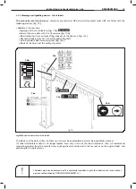
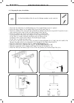
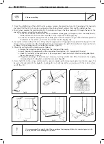
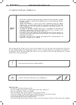
1. Screw tight the low nuts
2
on the log bolts
1,
leaving a threaded part up to have the corresponds protusion
ST,
(see “Fixing systems” on page 12) (fig. 21). Do the same operation on all 8 (eight) log bolts.
2. Insert all the logbolts
1
in the holes on the foundation frame
4,
so that the plate of the frame is resting on the nuts
and then tighten with the tall nuts
5,
interposing the washers
3.
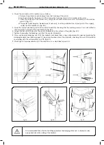
3. Sink the frame prepared in this way in the plinth casting, taking care that the upper plate remains on the same
level as the floor (fig. 22) Protect the threadings of the logbolts to avoid damage.
4. When needed, insert a tube into the plinth through which the electrical cable which powers the crane can be
passed (fig. 23).
5. Level the foundation frame using if necessary a bubble and proceed to the filling and flint-glazing of the plinth (fig. 24).
6. Wait the necessary time before assembling the column so that the plinth can stiffen.
fig.22
fig.21
fig.24
fig.23
5
4
3
2
1
2
1
KMAN05MG05

