30
INSTRUCTIONS JIB CRANE SERIES GBA - GBP
MAN05MGO5
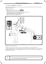
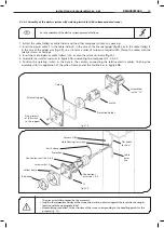
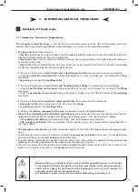
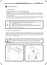
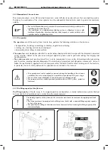
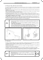
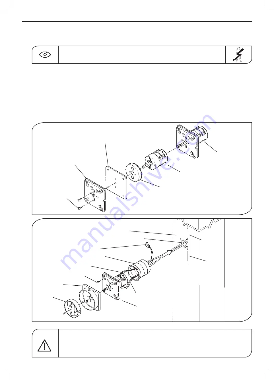
4.3.6.1 Assembly of the electric system with isolating switch for GBA column-mounted cranes
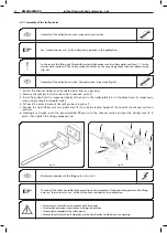
Fortheassemblyoftheelectricsystemproceedasfollows:
1. Extract the cable trolleys or cable sliders and the other components from any packing.
2. Insert the power cable
1
in the cable sliders
2
, in the case of the channel girger (fig.48), or in the cable trolleys
3
in the case of the girder arm (fig. 49), so as to form a series of festoons of equal width. Clamp the cables with the
relative screws or seatings.
3. Insert the cable sliders or cable trolleys into or onto the relevant jib arm (fig.50).
4. Assemble the isolator switch as in figure
51b
, assembling the components 1-2-3-4-5.
5. Position the isolating switch in the hole in the column, connecting the relative electric cables, finishing the
assembly with the application of the yellow frame and of the red knob as in figure
52b
.
Theuserorinstallerassignedbytheusermust:
•Installintheimmediatevicinityofthecrane,alineswitch,protectedagainstshortcircuits,showingits
function with the appropriate label.
•Haveearthingconnected,tothestructureofthecrane,correspondingtothehandlingpointsforthis
purpose
(fig. 53)
.
fig.52b
fig.51b
Assembled
switch “S1”
Gasket
External support
Fixing screws
of the switch
to the support
Red knob
S1
Yellow frame
Screws m4x10
Connections exit line 2-4-6
Connections
enter line 1-3-5
Cable
enter
line
Flat cable
for hoist
Protection
Earth clamp
Hole housing for switch
Column GBA
Switch
Protection holder
KMAN05MG05


