MAN05MGO5
INSTRUCTIONS JIB CRANE SERIES GBA - GBP
31
4.3.7 Assembly of the trolley/hoist
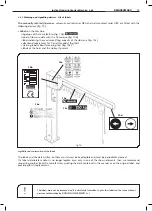
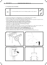
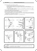
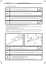
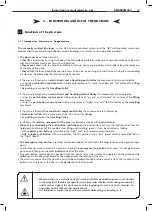
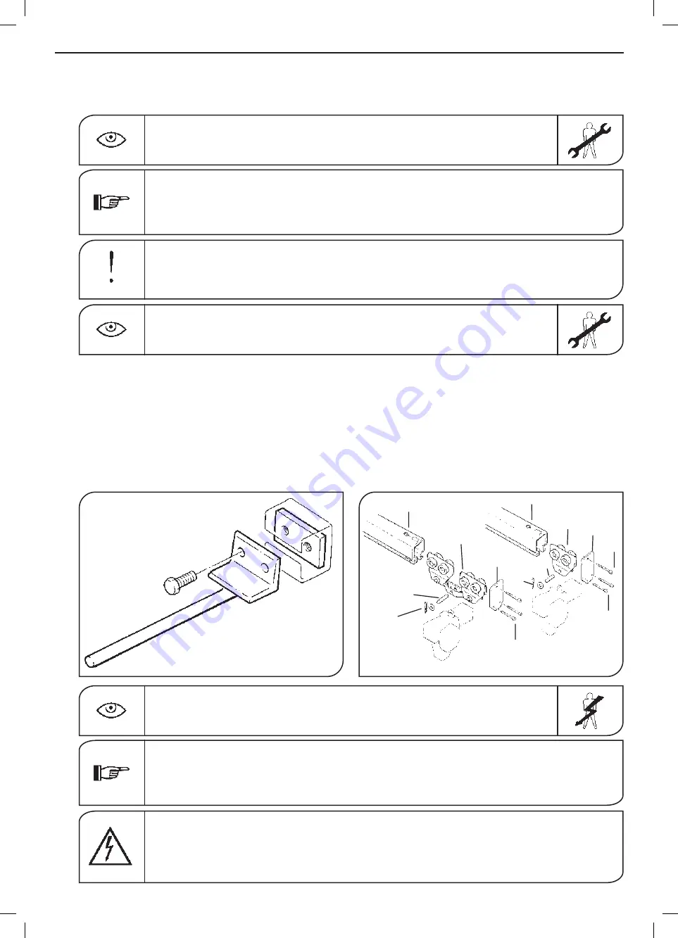
Assemblyofthetrolley/hoistonthe“channelsection”armcrane(fig.55):
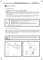
Assemblyofthetrolley/hoistonthecranewithasectionbar:
See“instructionsforuse”,ofthetrolley/hoist,includedinthispublication.
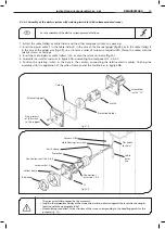
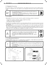
Electrical connections of the lifting unit
(trolley/hoist)
:
To connect the festooned cable of the power line to the terminals of the electrical apparatus of the lifting
unit,see“Instructionsforuse”,ofthetrolley/hoist,includedinthispublication.
•Nevercarryoutelectricalconnectionswithlivepower
•Nevermakeprecariousconnectionsorflyingconnections
•Clampdowncompletelythecablepresses
•Procuretheelectricalcircuitdiagramsforthehoist/trolleyonwhichyouareworking
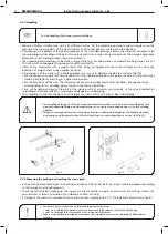
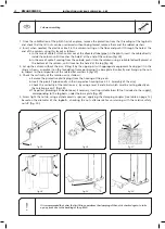
1. Extract the channel trolley and the related hoist from any packing.
2. Remove the split pin
1
and unscrew the suspension pivot
2.
3. Insert the eyebolt (or the suspension hook) of the hoist in the trolley plate
3
or in the brake beam
4,
respectively,
when using a simple or double trolley.
4. Put back the pivot
2
and put the split pin back in place
1.
5. Position the hoist/trolley unit on a pallet and lift this until the lead-in height of the head of the channel section is
reached.
6. Working at a height, insert the pre-assembled lifting unit in the channel section and put the closing cover
5
in
place, then tighten the fixing components
6
.
fig.55
fig.54
Inthecaseoftheliftingunitfittedwithelectrictrolley,makesurethestrikerplatesarefitted-1-,forthe
electric limit switches of the trolley, inside the blocks on the arm, fixing them with the related screws
(fig.54).
6
6
3
5
4
2
1
5
6
6
6
1
2
KMAN05MG05


