13
13
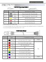
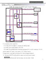
PIN No.
Color
Connection & Usage
①
Black
Communication TX(+) Signal
RS485
Communication
②
Brown
PLC Circuit HVPS Alarm Signal
PLC
③
Red
PLC Circuit Ground
④
Orange
NC
⑤
Yellow
PLC Circuit Clean Signal
⑥
Green
PLC Circuit On/Off Signal
⑦
Blue
PLC Circuit Fan Alarm Signal
⑧
Violet
Communication TX(-) Signal
RS485
Communication
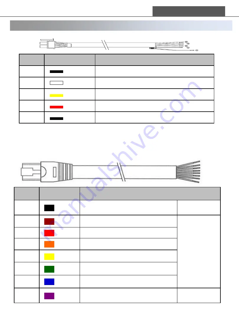
< RJ45 Cable Wiring>
DONG IL TECHNOLOGY LTD
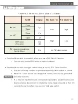
2.2 Wiring diagram
PIN No.
Color
Connection & Usage
①
Black
Power Ground (DC Power Ground)
②
White
Power Ground (DC Power Ground)
③
Yellow
+24V DC Power Supply
④
Red
+24V DC Power Supply
⑤
Black
Ground (Field Ground)
< 24V DC Power Input Cable >
24V DC power input cable wiring
1) Connect Black(short) wire & White wire to power ground and Black(long) wire to field ground.
2) Connect Red wire and Yellow wire to DC + 24V.
①
②
③
④
⑤
⑥
⑦
⑧


