


CPRS-1400,1400D INSTALLATION MANUAL
Issue : 2004.07
ED : 0
CPRS-1400,1400D INSTALLATION MANUAL 32 /47
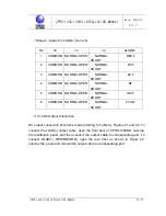
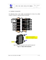
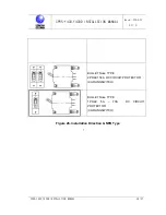
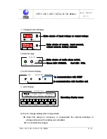
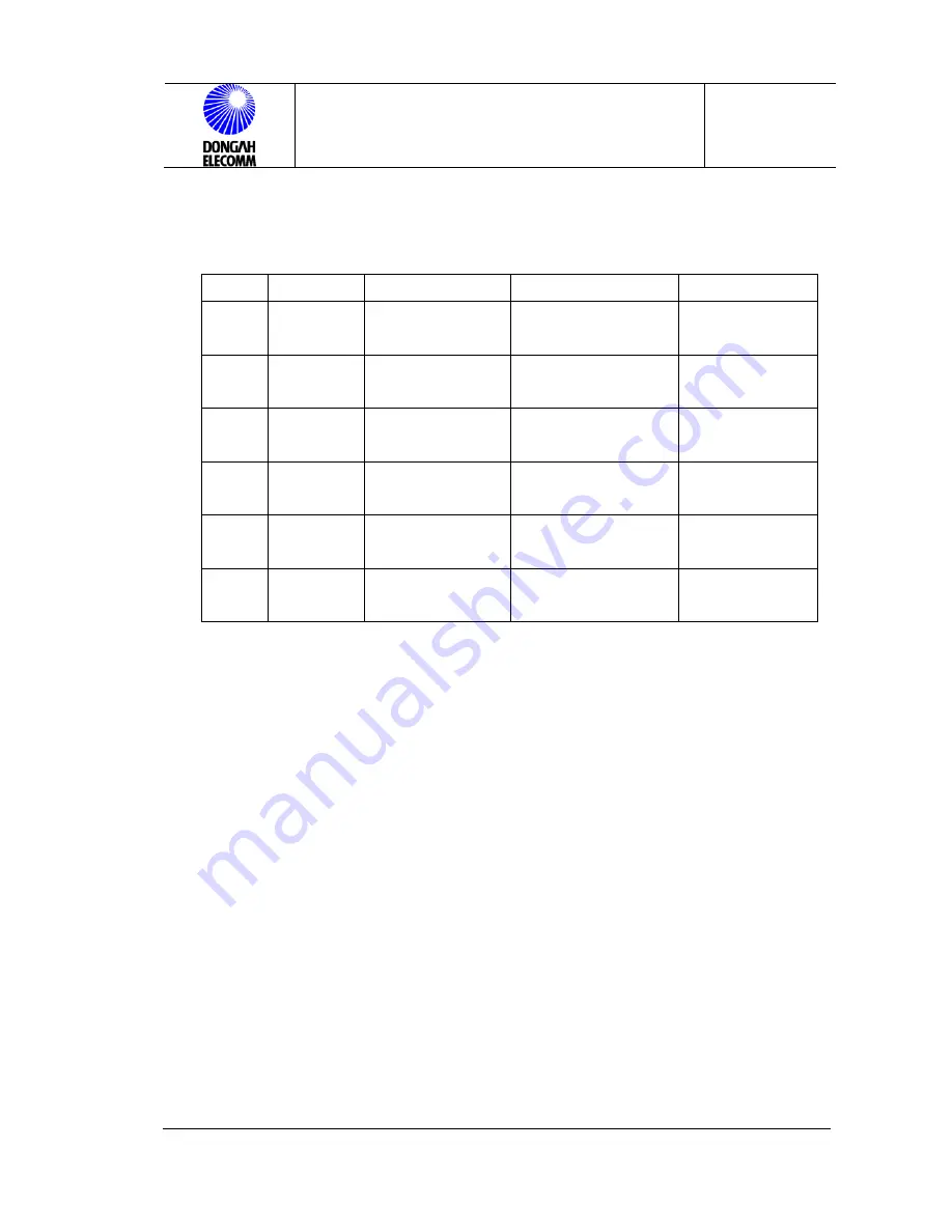
<Table 2>. Alarm Pin TABLE (J3,J4,J5)
No J5
J3
J4
ALARM
1 COMMON
NORMAL
OPEN
NORMAL
SHORT
RECF
2 COMMON
NORMAL
OPEN
NORMAL
SHORT
DCF
3 COMMON
NORMAL
OPEN
NORMAL
SHORT
ACF
4 COMMON
NORMAL
OPEN
NORMAL
SHORT
BF
5 COMMON
NORMAL
OPEN
NORMAL
SHORT
INVF
6 COMMON
NORMAL
OPEN
NORMAL
SHORT
CTRLF
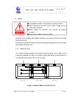
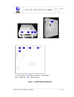
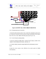
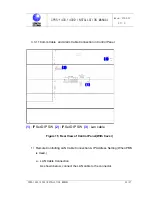
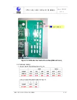
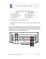
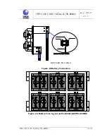
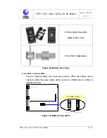
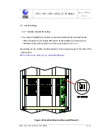
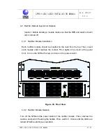
3.3.12 DC Output Connection
DC output connection should be made referring to Table 4), Figures 21 and 22. To
connect the LOAD(-) output cable, open the front door of CPRS-1400DD, unscrew
the distribution panel, and then connect the output cable to corresponding port. To
connect LOAD(+) RETURN(GND), open the rear door as shown in Figure 22,
unscres the panel and connect the output cable to corresponding port.


