background image


Written Date 

2010.05.30 


Document No.


Change code 

File/Reference 

Operation Manual.DOC


Page 


(4/21) 


                                                                  DONGAH ELECOMM R&D CENTER     

                              All rights are reserved.


2. Installation

2.1 Packing Condition 

            All power shelf equipment is shipped out using standard packing methods for DongAh rectifier systems. 


2.2 Transportation   

This power equipment shall be treated with special care as there is possibility of product damage due to 

severe  impact  or  vibration  during  transport.  Moreover,  transporting  equipment  using  car  or  other  non-

traditional carrier method must still protect the equipment from rain and other environmental hazards. 


2.3 Packing / Disassembly 

Unpack  and  disassemble  the  equipment  as  near  as  pos sible  to  point  of  installation,  and  pay  attention 

that no impurities get onto or inside the equipment . 


2.4 Wiring and Cable Connections

2.4.1 Connection Diagram of AC Input Connection(s) and Direct Current Output Terminal Block 

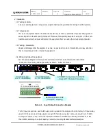
  Connect AC input wiring and output wiring as shown  below in Picture 1

DC OUTPUT(-48V)

L1~L10, 12AWG MAX

DC OUTPUT(GND)

L1~L10, 12AWG MAX

SLOTTED

SCREW

MAXIMUM 12AWG WIRE 

[ 10mm(0.4") stripping ]


Picture 1.    Input/Output Connection Diagram   


For AC Input connections, ues the IEC-style cords included in the shipment from the factory. AC Input wiring

uses IEC-C14 panel-mount male plugs to accept C13 female connectors; cable wire should be 8-10 AWG.

DC output connector uses a wire with maximum thickness of 12AWG, and can adjust thickness to less 

than 12AWG according to output capacity. Connect wires using standard slotted screwdriver. 

AC INPUT Connectors: (3) IEC-C14

--Accepts C13 Female Connectors--

Summary of Contents for DIRS-4110

Page 1: ...tion manual DOC Page 1 23 Written by Kim Sang Ho Review Oh Gyeong Seung Approved by Kim Hong Joong Document administrator Kim Sang Ho Title DIRS 4110 Operation Manual Document Type DONGAH ELECOMM R D CENTER All rights reserved DIRS 4110 Power Supply Shelf Operation Manual ...

Page 2: ... Connections 3 Rectifier System Shelf Components and Functions 3 1 Shelf DIRS 4110 3 2 Control Module DIRC 4 3 3 Rectifier Module DRM 440H44R0 4 System Management 4 1 Normal Operating Condition 5 Rectifier System 5 1 Rectifier System Operating Principles 5 2 Rectifier System Block Diagram 5 3 Initial Inspection and Power Up 6 Rectifier Module 6 1 Rectifier Module Operating Principles 6 2 Rectifier...

Page 3: ...t Distribution 10 individual circuits L1 L10 GMT fuses 10A each 1 3 Environmental Properties 1 3 2 Operating Humidity Range 10 90 RH non condensing 1 4 Safety Standards 1 4 1 Lightning Surge INPUT terminal EARTH 1 2 50us 2KV between INPUT terminals 1 2 50us 1KV 1 4 2 Insulation Resistance 500Vdc and 10MΩ 1 4 4 High Frequency Electromagnetic Interference EMI EN55022 Level B 1 5 Protection Functions...

Page 4: ...o point of installation and pay attention that no impurities get onto or inside the equipment 2 4 Wiring and Cable Connections 2 4 1 Connection Diagram of AC Input Connection s and Direct Current Output Terminal Block Connect AC input wiring and output wiring as shown below in Picture 1 DC OUTPUT 48V L1 L10 12AWG MAX DC OUTPUT GND L1 L10 12AWG MAX SLOTTED SCREW MAXIMUM 12AWG WIRE 10mm 0 4 strippin...

Page 5: ...anel of the DIRC 4 control module and it is used by attaching a standard Ethernet cable to the TCP IP port 3 Rectifier System Shelf Components and Functions A full Rectifier System consists of 1 1U Shelf 1 Control Module 3 Rectifier Modules and 1 Distribution Panel Picture 3 diagrams a 19 Shelf with the DIRC 4 Control Module 3 DIRS 440 Rectifier Modules Picture 3 DIRS 4110 Shelf Diagram Front TCP ...

Page 6: ... via the rear panel connector Picture 4 GMT FUSE Diagram Front 3 2 Control Module DIRC 4 3 2 1 Main Control Module The DIRC 4 Control Module controls and monitors the status of the rectifier modules The Control Module also sends all alarms that may occur during Rectifier System operation Picture 5 DIRC 4 Control Module Front No Rectifier Status LED Status Note 3 AC Fail DC Fail Fuse Open Rectifier...

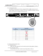
Page 7: ...UG port located on shelf rear Pin Assignment Description Control Module Rear Debug 8Pin RJ45 1 Reserved 2 TXD 3 RXD 4 Reserved 5 GND 6 Reserved 7 Reserved 8 Reserved 3 2 2 Measuring and Observation Function 3 2 2 1 Measuring Function Measure DC output voltage and DC output current then send it to Debug RS232 or Ethernet 3 2 2 2 Alarm Observation Function Monitor DC NFB and DC FUSE then send it to ...

Page 8: ...as needed to deliver the regulated 54V 50A per module to the load Each rectifier actively current shares and is hot swappable Warning If variable volume of the upper part of m 1 Green LED NOR Indicates Normal Rectifier status no alarms or failures 2 Red LED FAIL Indicates Failed Rectifier status greater than 280VAC DC Output protective device open No Fuse Breaker NFB or GMT Fuse Vadj allows fine t...

Page 9: ... DRM 440 Rectifier Modules a DIRC 4 Control Module and a Power Distribution block The system accepts an 85 264VAC single phase input filters rectifies and delivers a well regulated factory set 54V output at 111A with 3 rectifiers at 37A each screw lock into 2 10 terminal block load connectors one for 54V and one for GND at rear of the shelf Designed to efficiently and reliably power a customer s s...

Page 10: ... are tight and secure 5 3 2 Rectifier System Power Up 5 3 2 1 When preliminary inspection is complete confirm the AC input voltage is within specifications that all output cables are connected properly between the Rectifier System outputs and the inputs to the customer s system loads 5 3 2 2 Power On a Apply AC Input power to shelf b Confirm that the Rectifier Modules DRM 440 operate normally by o...

Page 11: ...ransformer rectified and filtered to deliver the 54V 37A output The Main PWM Control provides the regulation and loop response Detailed circuit descriptions are below Rectifier Module System Diagram 6 2 Rectifier Module Circuit Description 6 2 1 Input Circuit The input circuitry passes Input AC through a No Fuse Breaker NFB an EMI Filter and Inrush Control The Bridge Rectifier converts the AC into...

Page 12: ...ws energy stored in the PFC Inductor to transfer into the PFC DC Bus capacitor d PFC Control Circuit The PFC Control Circuit feeds a 66KHz PWM gate signal to the PFC FET The duty cycle of the PWM 6 2 5 Main Switching Circuit The Main Switching circuit uses a FET switched DC to transfer power across the main transformer The Main Switching Circuit operates as follows a Main FET The Main FET switches...

Page 13: ...0 within 120 after chopping pulsating voltage as 75 within 120 and a circuit that protects by shutting down output of the rectifier when output 300V becomes low tension due to disorder of feedback loop and element 6 2 9 PWM Control Circuit Main circuit part It is composed of feedback circuit that controls output voltage operating circuit that operates the main switch and soft start circuit to elim...

Page 14: ...nitor operation of maximum 3 of control modules DRM 440 7 1 2 Alarm Function 7 1 2 1 AC Input Fail It occurs when Input AC voltage of rectifier less than 180V and more than 280V LED turns to red light at the front panel 7 1 2 2 DC High Voltage It occurs when output voltage of rectifier is more than 58 0V LED turns to red light at the front panel Changing setting value to Debug Port and SNMP is pos...

Page 15: ...R D CENTER All rights are reserved 7 2 Control Module Block Diagram 7 3 Debug Operation 7 3 1 Function of Monitor Program Rectifier operation status inquiry Output voltage current alarm status of rectifier module Setting network information setting is possible Can set up the upper lowest limit of measuring alarm ...

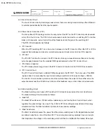
Page 16: ...o Change code 0 File Reference Operation Manual DOC Page 16 21 DONGAH ELECOMM R D CENTER All rights are reserved 7 3 2 Run pDIRS_4110 exe Try to connect by pushing Connect button If connection fails reset the port initially set as COM1 ...

Page 17: ...ce Operation Manual DOC Page 17 21 DONGAH ELECOMM R D CENTER All rights are reserved If connection is successfully made status of rectifier is shown as the above For now Rectifier Status section is shown and push Ethernet Info section in order to see other section ...

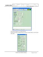
Page 18: ...ing Setting icon check V and push Setting to change rectifier module ON OFF and output voltage setting Reenter each section by clicking Alarm icon check V and push Setting to change alarm setting value of DC HIGH VOLT DC LOW VOLT Push Initial Alarm icon In order to change DC HIGH VOLT DC LOW VOLT alarm as the basic setting value Basic setting DC HIGH VOLT 58V DC LOW VOLT 48V ...

Page 19: ...le Reference Operation Manual DOC Page 19 21 DONGAH ELECOMM R D CENTER All rights are reserved Show rectifier IP and server IP in Ethernet Info tab Reenter each section by pushing IP Setting icon check V and push Setting in order to change setting value ...

Page 20: ...ew 7 4 2 1 Fill in IP and Site name Content is specified by clicking button 7 4 2 2 Repeat content of 7 4 2 1 in order to add 7 4 2 3 To change content write content in IP and Site section after clicking the relevant content and then click button 7 4 2 4 If to erase content select the relevant section and push button 7 4 2 5 Connection is made when button is pushed after content is specified 7 4 2...

Page 21: ... R D CENTER All rights are reserved 7 4 2 7 If alarm occurs site name and time are written on the below blank 7 4 2 8 Click button to save current IP and site name It takes about 5 sec to save 7 4 2 9 Information of the relevant site is shown as the below window Information of the selected site can be seen here ...

Reviews: