VPRS-4175E OPERATION MANUAL
Issue : 2009.03
ED : 1
VPRS-4175E OPERATION MANUAL 35 /31
1) Take care not to block the air ventilation holes with dusts or other alien
materials.
2) Check the connection and tightening state of cables.
3) Check if internal temperature of the site is maintained in rated level.
4) Check rectifier operation state and alarm state with naked eye.
5) Check fixing on the floor and water leakage on the installation site for the
rectifier system.
9.3 Adding Rectifier Module
To expand the system capacity, rectifier modules may be inserted to vacant slots.
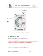
1) Check if the Standby/Operate switch of the module is set to ‘Standby’.
2) Insert a rectifier module to a corresponding slot, and tighten the captive screw
on it.
3) Set Standby/Operate switch of the module to ‘Operate’.
4) Control panel will automatically set current limit of rectifier.
As current limit is set to 50% or 110%, current limitation is made considering
the number of rectifier modules within this range.
5) Verify the voltage and current set on the LCD screen.
* Check load share of each rectifier unit. For details, see Control Panel Operation
Manual.
6) If total current does not increase after a new module is inserted, check if the
module has any problem on it, and check the ID setting of the rectifier module.
7) Check if the rectififer generates any alarm or has any errors on it.

