10
DISASSEMBLY AND ASSEMBLY
- Cautions to be observed when trouble shooting.
Unlike many other appliances, the microwave oven is high-voltage, high-current equipment. It is completely safe
during normal operation. However, carelessness in servicing the oven can result in an electric shock or possible
danger from a short circuit. You are asked to observe the following precautions carefully.
1. Always remove the power plug from the outlet before servicing.
2. Use an insulated screwdriver and wear rubber gloves when servicing the high voltage side.
3. Discharge the high voltage capacitor before touching any oven components or wiring.
(1) Check the grounding.
Do not operate on a two-wire extension cord.
The microwave oven is designed to be used while grounded.
It is imperative, therefore, to make sure it is grounded
properly before beginning repair work.
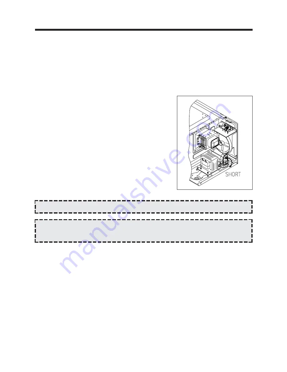
(2) Warning about the electric charge in the high voltage capacitor.
For about 30 seconds after the operation has stopped, electric
charge remains in the high voltage capacitor.
When replacing or checking parts, short between oven chassis
and the negative high terminal of the high voltage capacitor by
using a properly insulated screwdriver to discharge.
4. When the 12A fuse is blown due to the operation of the monitor
switch; replace primary interlock switch, secondary interlock switch
and interlock monitor switch.
5. After repair or replacement of parts, make sure that the screws are
properly tightened, and all electrical connections are tightened.
6. Do not operate without cabinet.
CAUTION :
Service personnel should remove their watches whenever working close to or replacing the magnetron.
WARNING :
When servicing the appliance, take care when touching or replacing high potential parts because of
electrical shock or exposing microwave. These parts are as follows - HV Transformer, Magnetron,
HV Capacitor, HV Diode, HV Fuse.
Summary of Contents for KOR-164H0W
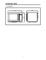
Page 5: ...5 EXTERNAL VIEW 1 OUTER DIMENSION ...
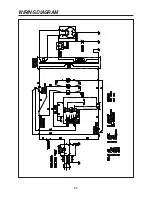
Page 25: ...25 WIRING DIAGRAM ...
Page 27: ...27 Measure Point MP1 GND MP2 ...
Page 29: ...29 2 PCB CIRCUIT DIAGRAM ...

