background image

raise the blade and counterclockwise 

to lower it. (

Fig. 10

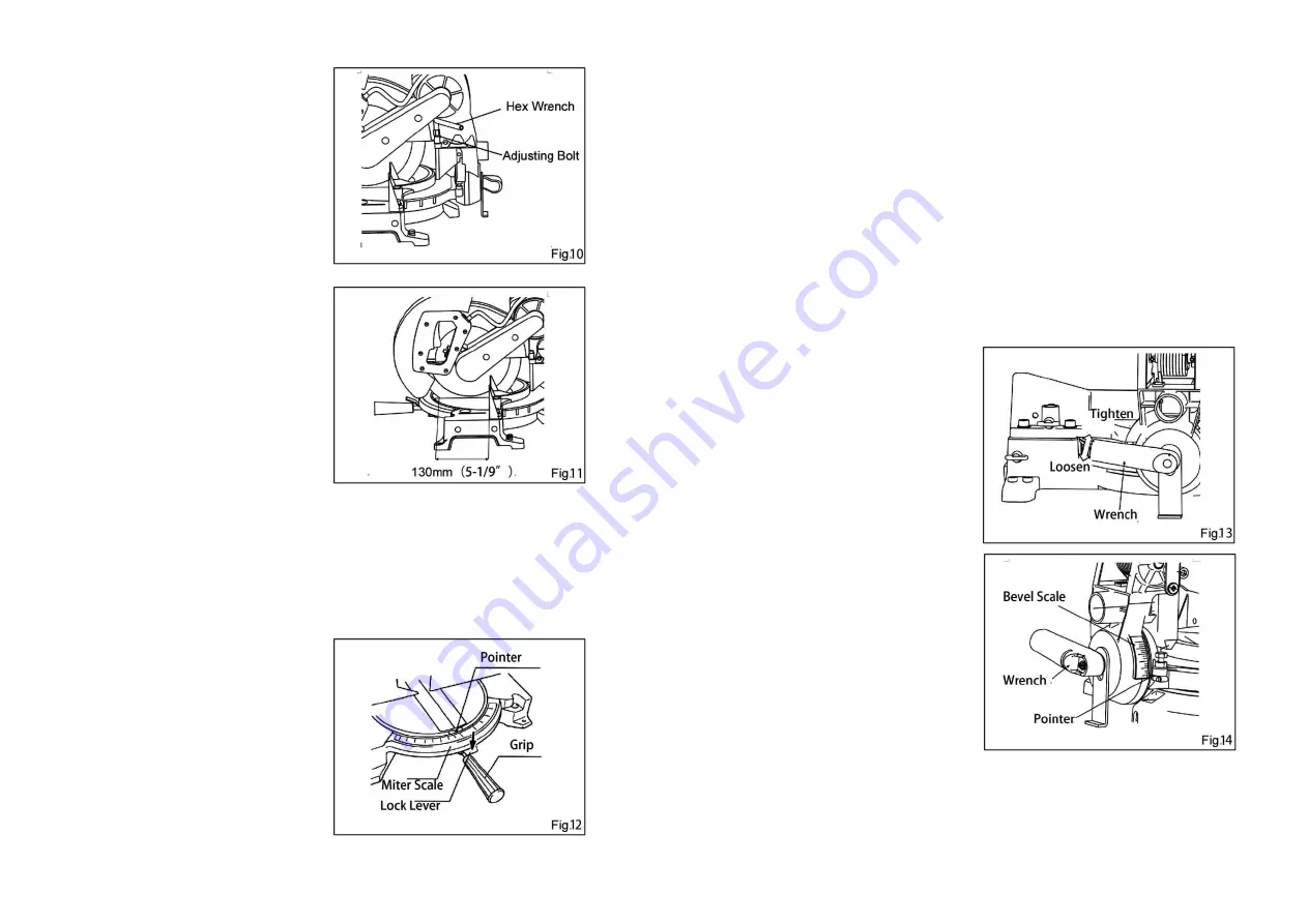
Refer  to  the  following  procedures  for 

the adjustment: 

Unplug the tool and lower the handle 

completely, use the socket wrench to 

turn  the  adjusting  bolt  until  the 

distance between the front face of the 

guide fence and the front point where 

the  blade  crossing  with  the  top 

surface  of  the  turn  base  meets  130 

mm (5-1/9

”). (

Fig. 11

With  the  tool  unplugged,  rotate  the 

blade  by  hand  while  holding  the 

handle  all  the  way  down  to  be  sure 

that  the  blade  does  not  contact  any 

part  of  the  lower  base.  Re-adjust 

slightly, if necessary. 


Adjusting the Miter Angle 

CAUTION: 

 Be  sure  to  raise  the  handle  fully 

while turning the turn base. 

Loosen  the  grip  by  turning  it 

counterclockwise.  Turn  the turn  base 

while  pressing  down  the  lock  lever. 

When the grip has been moved to the 

position  where  the  pointer  points  to  the  desired  angle  on  the  miter  scale,  securely 

tighten the grip clockwise. (

Fig. 12


Adjusting the Bevel Angle 

CAUTION: 

 Be sure to raise the handle fully while tilting the saw blade. 

 The saw blade can be tilted at 45° to the left only when the sub-fence locates at the 

left position (

refer to the instructions of 

Sub-fence

). 

  After  changing  the  bevel  angle,  always  secure  the  arm  by  tightening  the  lever 

clockwise. 

To  adjust  the  bevel  angle,  loosen  the  lever 

at the rear of the tool counterclockwise. (

Fig. 

13


Push  the  handle  to  the  left  to  tilt  the  saw 

blade  until  the  pointer  points  to  the  desired 

angle  on  the  bevel  scale.  Then  tighten  the 

lever  clockwise  firmly  to  secure  the  arm. 

(

Fig. 14


-11-                                                                            -12-


Summary of Contents for DJX03-255

Page 1: ...Edition 2 Feb 2017 Read through carefully and understand these instructions before use ...

Page 2: ...r use reduces the risk of electric shock 9 If operating a power in a damp location is unavoidable use a residual current device RCD protected supply Use of an RCD reduces the risk of electric shock NOTE The term residual current device RCD may be replaced by the term ground fault circuit interrupter GFCI or earth leakage circuit breaker ELCB Personal Safety 10 Stay alert watch what you are doing a...

Page 3: ...g only identical replacement parts This will ensure that the safety of the power tool is maintained VOLTAGE WARNING Before connecting the machine to a power source receptacle outlet etc be sure the voltage supplied is the same as that specified on the nameplate of the machine A power source with voltage greater than that specified for the machine can result in SERIOUS INJURY to the user as well as...

Page 4: ...it until the blade attains full speed before cutting 16 Hold the handle firmly during operation Be aware that the saw moves up or down slightly during start up and stopping 17 Stop operation immediately if anything abnormal be noted 18 Do not attempt to lock the switch trigger in the ON position 19 Be alert at all times especially during repetitive monotonous operations Do not be lulled into a fal...

Page 5: ...or remove the blade Failure to do so may result in overtightening or insufficient tightening of the hex bolt This could cause an injury After installing a new blade always be sure that the blade does not contact any part of the lower base when the handle is lowered completely Always do this with the tool unplugged To remove the saw blade turn lower safety guard to exceed the position of the screw ...

Page 6: ...y that the blade is no longer easily visible unplug the saw and clean the guard carefully with a damp cloth Dust Bag The use of the dust bag makes cutting operations clean and dust collection easy To attach the dust bag fit it onto the dust nozzle Fig 8 Switch Action CAUTION Before plugging in the tool always check to see that the switch trigger actuates properly and returns to the OFF position wh...

Page 7: ...rn base Loosen the grip by turning it counterclockwise Turn the turn base while pressing down the lock lever When the grip has been moved to the position where the pointer points to the desired angle on the miter scale securely tighten the grip clockwise Fig 12 Adjusting the Bevel Angle CAUTION Be sure to raise the handle fully while tilting the saw blade The saw blade can be tilted at 45 to the l...

Page 8: ...avoid blade pinch and possible KICKBACK The vertical vise can be installed in two positions on either the left or right side of the guide fence or the holder assembly optional accessory Insert the vise rod into the hole in the guide fence or the holder assembly and tighten the screw to secure the vise rod Position the vise arm according to the thickness and shape of the workpiece and secure the vi...

Page 9: ... lower the handle to begin the cutting operation When the cut is completed switch off the tool and wait until the blade has come to a complete stop before returning the blade to its fully elevated position Miter Cutting Refer to the instructions of Adjusting the Miter Angle Bevel Cutting CAUTION Always set the sub fence to the left position when performing left bevel cuts Always be sure that the b...

Page 10: ... that the tool is switched off and unplugged before attempting to perform inspection or maintenance Always keep the blade sharp and clean for the best and safest performance Adjust the Cutting Angle This tool is carefully adjusted and aligned before leaving the factory but rough handling may have affected the alignment If the tool is not aligned properly perform the following to readjust Miter Ang...

Page 11: ...er does not point to 45 turn the adjusting bolt B on the left side of the arm until the pointer points to 45 Fig 27 After Use After use wipe off chips and dust adhering to the tool with a cloth or the like Keep the blade guard clean according to the directions in the previously covered section titled Blade Guard Lubricate the sliding portions with machine oil to prevent rust Inspecting and Replaci...

Page 12: ... 21 22 ...

Page 13: ...ew with Spring Washers 58 Sleeve 28 Flat Washer 59 Cross Recessed Countersunk Head Screw 29 Hex Nut 60 Safety Guard 30 Nut 61 Lower Safety Guard EXPLANATION OF GENERAL VIEW 62 Screw 92 Compression Spring 63 Torsion Spring 93 Locking Pin 64 Rubber Sleeve 94 Bracket 65 Pan Head Screw with Flat and Spring Washers 95 Cover 66 Pan Head Screw with Flat Point 96 Pan Head Screw 67 Fixed plate 97 Hex Lock ...

Reviews: