background image

6.  Under normal operation, the tool is designed to produce vibration. The screws 

can come loose easily, causing a breakdown or accident. Check tightness of 

screws carefully before operation. 

7.  Under normal operation, the tool is designed to produce vibration. The screws 

can come loose easily, causing a breakdown or accident. Check tightness of 

screws carefully before operation. 

8.  Always be sure to have a firm footing. Wear safety belt when using this tool in 

high locations and ensue no one is below. 

9.  Keep hands away from the rotating parts. 

10. Do not leave the tool running. Operate the tool only when hand-held. 

11. Do not point the tool at any one in the area when operating. The bit could fly 

out and injure someone seriously. 

12. Do not touch the bit or parts close to the bit immediately after operation; they 

may be extremely hot and could burn your skin 

SAVE THESE INSTRUCTIONS. 

WARNING! 

MISUSE  or  failure  to  follow  the  safety  rules  stated  in  this 

instruction manual may cause serious personal injury. 


INSTRUCTIONS FOR OPERATION 

Setting Operating Mode 

Caution: 

 Always  be  sure  that  the  tool  is  switched  OFF  before  changing  the  operating 

mode, or the gears inside the tool maybe damaged. 

 If the drill bit gets stuck by the steel hidden in the wall during impact drilling, and 

the tool rotates due to the kickback, hold the handle and auxiliary handle firmly 

to avoid personal injuries. 

The Operating mode can be changed by turning the 

operating mode selector. 

Drilling Operation 

When impact drilling on the concrete or stone, turn the selector to the position as 

shown in the figure. 

When  normally  drilling  on  the  wood,  metal,  ceramics  or 

plastic,  turn  the  selector  to  the  position  as  shown  in  the 

figure.   


Demolition Operation 

When  the  position  of  chisel  needs  adjusting  during 

operation, turn the selector to the position as shown in the 

figure  to  avoid  gears  from  meshing  and  then  adjust  the 

chisel.

Z1C-FF05-26/Z1C-FF05-26B


After  adjusting  the  chisel,  turn  the  selector  to  the  position 

as shown in the figure to restart demolition operation. 
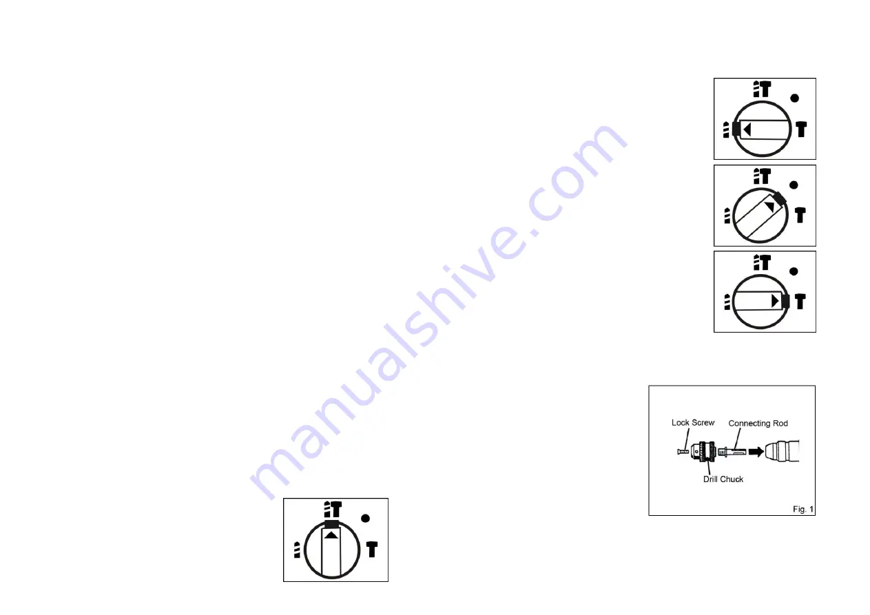


Installing


SDS-plus Hammer Drill Bit 

SDS-plus  hammer  drill  bit  can  be  used 

when drilling on the steel, wood or plastic. 

Screw the drill chuck in the connecting rod 

and tighten the lock screw. Then insert the 

connecting rod into the collect in the same 

way as installing SDS-plus hammer drill bit. 

SDS-plus  hammer  drill  bit  and  drill  chuck 

are optional accessories. 

(Fig. 1)


Installing /Removing Drill Bit


-5-                                                                            -6-


Summary of Contents for DZC05-26

Page 1: ...Edition 3 Jan 2017 Read through carefully and understand these instructions before use ...

Page 2: ...r use reduces the risk of electric shock 9 If operating a power in a damp location is unavoidable use a residual current device RCD protected supply Use of an RCD reduces the risk of electric shock NOTE The term residual current device RCD may be replaced by the term ground fault circuit interrupter GFCI or earth leakage circuit breaker ELCB Personal Safety 10 Stay alert watch what you are doing a...

Page 3: ...placement parts This will ensure that the safety of the power tool is maintained VOLTAGE WARNING Before connecting the machine to a power source receptacle outlet etc be sure the voltage supplied is the same as that specified on the nameplate of the machine A power source with voltage greater than that specified for the machine can result in SERIOUS INJURY to the user as well as damage to the mach...

Page 4: ...ing the operating mode or the gears inside the tool maybe damaged If the drill bit gets stuck by the steel hidden in the wall during impact drilling and the tool rotates due to the kickback hold the handle and auxiliary handle firmly to avoid personal injuries The Operating mode can be changed by turning the operating mode selector Drilling Operation When impact drilling on the concrete or stone t...

Page 5: ...n tighten it by turning clockwise Fig 4 Switch Action CAUTION Before plugging in the tool always check to see that the trigger switch actuates properly and returns to the OFF position when released To start the tool simply pull the switch trigger Release the switch trigger to stop For continuous operation pull the switch trigger and then push in the lock lever To stop the tool from the locked posi...

Page 6: ...o so could result in serious hazard 3 Maintenance of the Motor The motor unit winding is the very heart of the power tool Exercise due care to ensure the winding does not become damaged and or wet with oil or water 4 Inspecting and Replacing Carbon Brushes Remove and check the carbon brushes regularly Replace when they wear down to the limit mark Keep the carbon brushes clean and free to slip in t...

Page 7: ...Z1C FF05 26 Z1C FF05 26B 11 12 ...

Page 8: ...Sleeve 37 Damping Washer 11 O Ring 38 O Ring 12 Seal Ring 39 Adaptor Sleeve 13 Thrust Ring 40 Roundwire Snap Ring for Hole 14 Impact Bolt 41 Striker 15 Label 42 O Ring 16 Gear Housing 43 Piston 17 Seal Ring 44 Washer 18 Needle Bearing 45 Piston Pin 19 Needle Bearing Cover 46 Shaft Sleeve 20 Clamping Ring 47 Seal Ring 21 Operating Mode Selector 48 Metal Sheet for Support 22 O Ring 49 Gear Housing C...

Page 9: ...sing 80 Carbon Brush Holder 81 Carbon Brush EXPLANATION OF GENERAL VIEW Z1C FF05 26B 1 Dust Cap 28 Clutch Spring 2 Roundwire Snap Ring for Shaft 29 Roundwire Snap Ring for Shaft 3 Washer 30 Clutch Gear 4 Roundwire Snap Ring 31 Lock Pin 5 Locking Sleeve 32 Cylinder 6 Clamping Ring 33 Pin 7 Steel Ball 34 Clutch Plate 8 Clip Board 35 Retaining Ring for Hole 9 Compression Spring 36 Guide Sleeve 10 Ret...

Page 10: ...79 Motor Housing 80 Carbon Brush Holder 81 Carbon Brush EXPLANATION OF GENERAL VIEW Z1C FF05 26C 1 Dust Cap 28 Clutch Spring 2 Roundwire Snap Ring for Shaft 29 Roundwire Snap Ring for Shaft 3 Washer 30 Clutch Gear 4 Roundwire Snap Ring 31 Lock Pin 5 Locking Sleeve 32 Cylinder 6 Clamping Ring 33 Pin 7 Steel Ball 34 Clutch Plate 8 Clip Board 35 Retaining Ring for Hole 9 Compression Spring 36 Guide S...

Page 11: ...ge 64 Deep Groove Ball Bearing 91 Steel Band 65 Bearing Retainer 92 Trapezoid Square neck Bolt 66 Cross Recessed Countersunk Head Screw 93 Lock Screw 67 Washer 94 Steel Band Base 68 Armature Assembly 95 Hex Nut 69 Insulation Washer 96 Clip Board 70 Ball Bearing 97 Auxiliary Handle 71 Rubber Sleeve 98 Nut 72 Baffle Plate 73 Pan Head Tapping Screw 74 Stator Assembly 75 Inductance 76 Nameplate 77 Mot...

Reviews: